
PWM Motor Speed Control Using Class D Audio Amplifier
The Class D audio amplifier circuit is designed to efficiently manage the speed of a PWM (Pulse Width Modulation) motor, making it particularly suitable for battery-operated portable devices. Class D amplifiers are known for their high efficiency, often exceeding 90%, which is crucial for extending battery life in portable applications.
In this circuit, the input audio signal is first processed and converted into a PWM signal. This conversion is achieved using a comparator that compares the input signal with a triangular waveform. The resulting PWM signal is then used to drive a power stage, typically consisting of MOSFETs or IGBTs, which switch on and off rapidly to control the power delivered to the motor.
The advantages of using a Class D amplifier for PWM motor control include reduced heat generation and improved battery efficiency. Since the switching elements operate in saturation and cutoff regions, power loss due to heat is minimized. This is particularly beneficial in applications where thermal management is critical.
Additionally, the circuit can incorporate feedback mechanisms to ensure precise control of motor speed and torque, enhancing the overall performance of the device. By adjusting the duty cycle of the PWM signal, the speed of the motor can be finely tuned, allowing for smooth operation across a range of speeds.
In summary, the Class D audio amplifier circuit for PWM motor speed control provides an effective solution for managing power in battery-powered devices, combining efficiency, performance, and the ability to maintain compact designs.This is class D audio amplifier circuit that is used to control PWM motor speed. This circuit has two advantages for battery-powered portable devices. First, . 🔗 External reference
Related Circuits
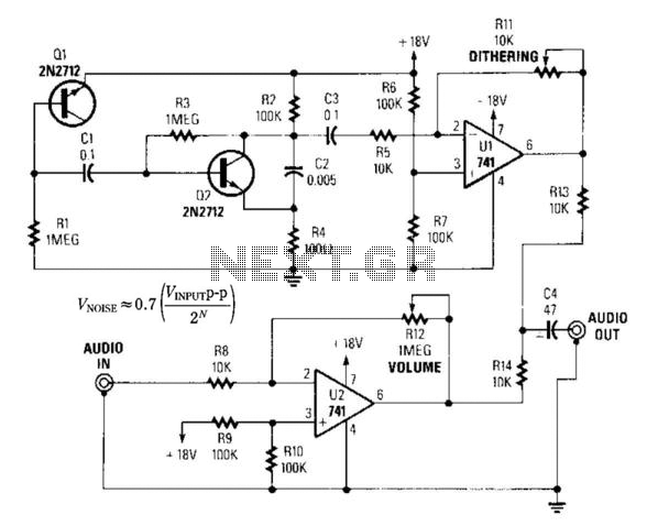
By introducing a small amount of noise to a signal intended for digitization (approximately 0.7 bits), where n represents the number of bits, for instance, an 8-bit signal with a peak-to-peak voltage of 2 V would result in a...
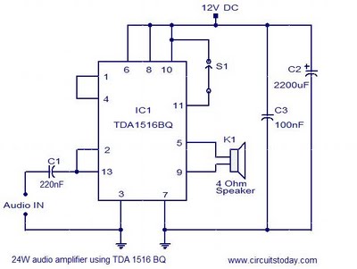
This document presents the circuit diagram of a simple 24W mono amplifier utilizing the TDA1516 integrated circuit. The TDA1516 is a Class B power amplifier housed in a 13-pin SIL package. It incorporates several beneficial features, including short circuit...
The simplest form of motor controllers, apart from a basic on/off switch, is the contactor controller. This contactor controller is recommended for use in electric scooter projects. It is based on three 12V relays, two 12V batteries, two switches,...
The integrated circuit (IC) is a quad 2-input "AND" gate, specifically a CMOS 4081. These gates output a HIGH signal only when both inputs are HIGH. When the key connected to pin E is pressed, current flows through resistor...
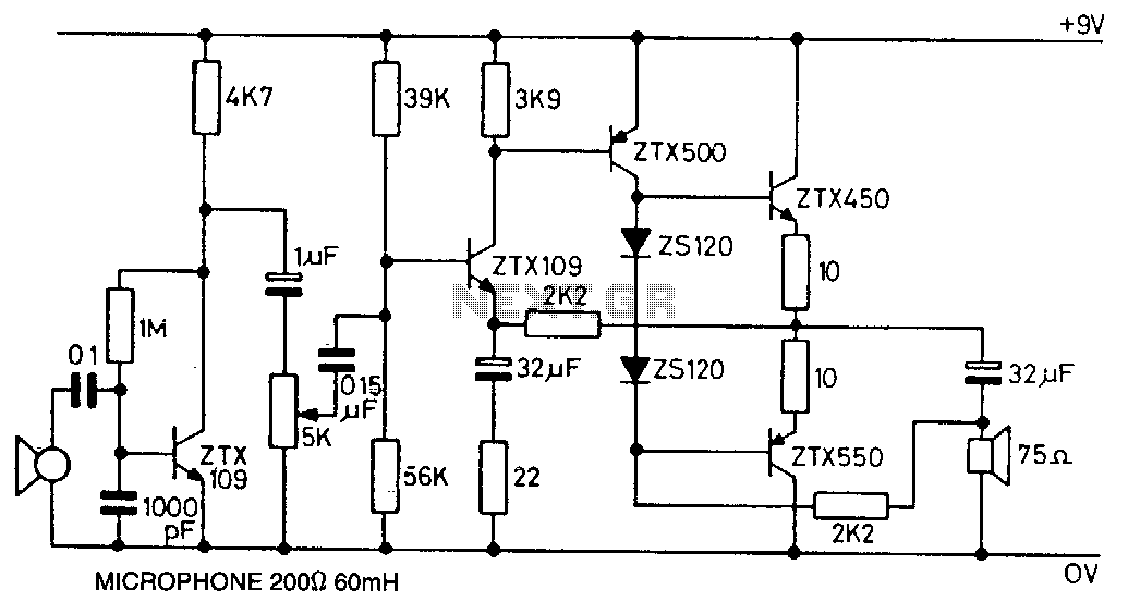
This circuit utilizes the ZTX450 and ZTX550 transistors configured in a push-pull output stage. The following measurements were recorded at maximum volume: Input: 0.4 mV rms, Output: 1.8 V rms, Voltage gain: 4500, Maximum output before distortion: 2.25 V...
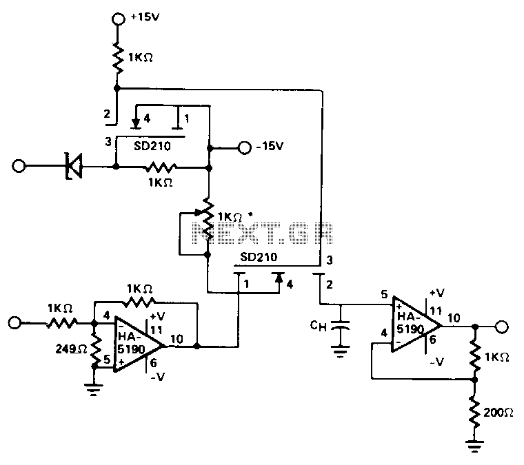
This circuit utilizes the speed and drive capability of the HA-5190 in conjunction with two high-speed DMOS FET switches. The input amplifier is configured to operate at a gain of -5, while the overall circuit gain remains at unity....
Warning: include(partials/cookie-banner.php): Failed to open stream: Permission denied in /var/www/html/nextgr/view-circuit.php on line 713
Warning: include(): Failed opening 'partials/cookie-banner.php' for inclusion (include_path='.:/usr/share/php') in /var/www/html/nextgr/view-circuit.php on line 713