
Birthday Heart circuit
The birthday heart circuit is designed to create a visually appealing display, often used as a decorative element for celebrations. The circuit typically utilizes a series of light-emitting diodes (LEDs) arranged in the shape of a heart to provide illumination. The heart shape can be created using a printed circuit board (PCB) or a simple breadboard setup, depending on the complexity desired.
Power for the circuit is usually supplied by a low-voltage source, such as a battery or USB power supply, ensuring safety and ease of use. A common choice for the power supply is a 5V source, which is compatible with most standard LEDs.
To control the LEDs, a microcontroller or a simple timer circuit can be employed. For example, a 555 timer IC can be configured in astable mode to create a blinking effect, enhancing the visual appeal of the heart circuit. Alternatively, a microcontroller such as an Arduino can be programmed to control the timing and patterns of the LED illumination, allowing for more complex light displays such as fading or chasing effects.
The circuit may also include resistors to limit the current flowing through the LEDs, preventing damage and ensuring longevity. The value of the resistors can be calculated based on the forward voltage and current specifications of the chosen LEDs.
For enhanced functionality, additional components such as a switch can be integrated to turn the circuit on and off, or a potentiometer can be included to adjust the brightness of the LEDs. This flexibility allows for customization based on user preferences.
Overall, the birthday heart circuit serves as an engaging and festive electronic project, combining basic electronic components with creative design to celebrate special occasions.This is a birthday heart circuit. No much description is available but you can use your expirienced imagination! ;) 🔗 External reference
Related Circuits
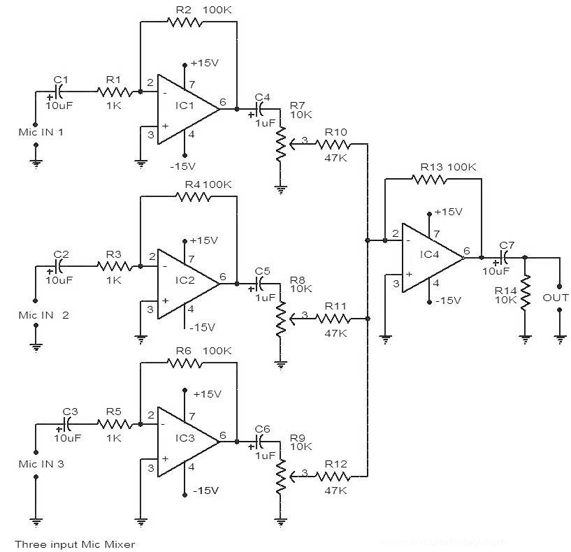
This is a circuit diagram of a 741 IC-based three-input microphone mixer circuit. A total of four 741 ICs are utilized, with IC1, IC2, and IC3 serving specific functions within the design. The circuit utilizes four operational amplifiers from the...

A 555 timer and a dual 556 timer are used to generate a basic video signal, as illustrated in the schematic. The first timer operates in astable mode, producing synchronization pulses with a period ranging from 4.7 to 8...
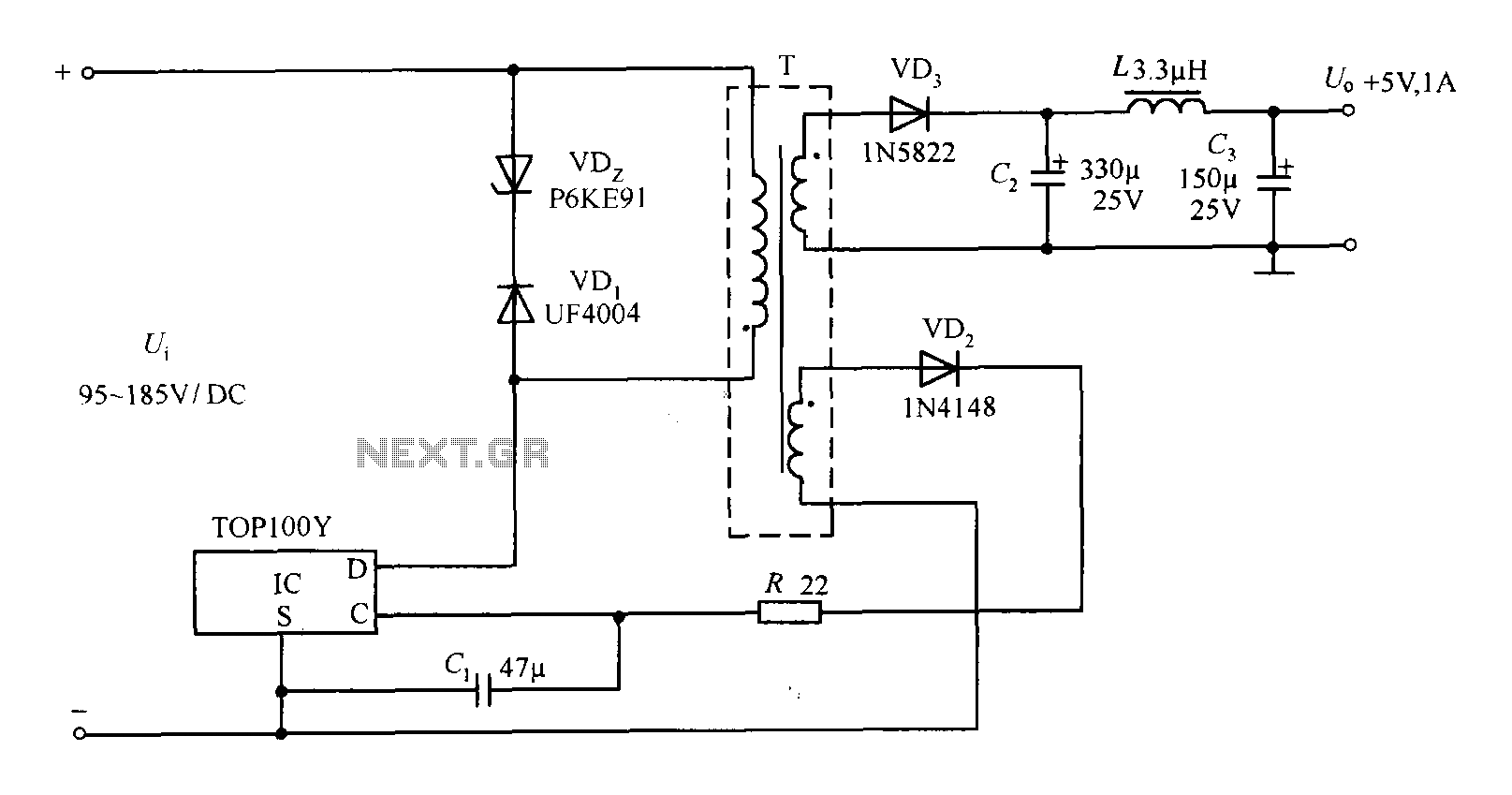
The TOP100Y is a flyback DC switching power supply circuit with a +5V, 1A output. This power supply features a feedback circuit that directly regulates the output voltage, making it suitable for applications that require electrical isolation and minimal...

AN12979A is a stereo BTL amplifier that includes an AGC circuit to prevent clipping at the speaker output. This integrated circuit (IC) can perform mode changes via the I2C bus control system, allowing for functions such as toggling the...
The LM1036 is a DC-controlled circuit designed for managing tone (bass/treble), volume, and balance in stereo applications, such as car radios, televisions, and audio systems. It features an additional control input for easy loudness compensation. Four control inputs allow...
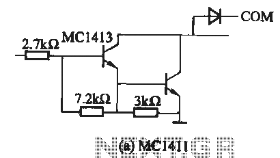
The MC1411 series is a Darlington driver with a compact, reliable internal structure. It is particularly suited for high-voltage applications, functioning effectively as a high-voltage peripheral driver. This driver can directly control relays, lights, and other loads. It is...
Warning: include(partials/cookie-banner.php): Failed to open stream: Permission denied in /var/www/html/nextgr/view-circuit.php on line 713
Warning: include(): Failed opening 'partials/cookie-banner.php' for inclusion (include_path='.:/usr/share/php') in /var/www/html/nextgr/view-circuit.php on line 713