
3 Input Mic Mixer Circuit
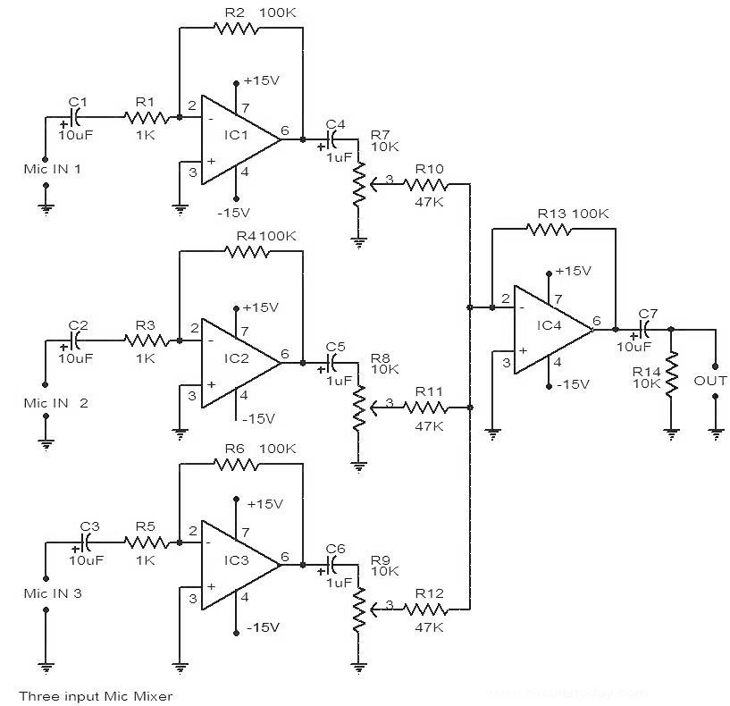
The circuit utilizes four operational amplifiers from the 741 IC series, which are well-known for their versatility in audio applications. The primary function of this mixer circuit is to combine audio signals from three different microphones into a single output, allowing for a unified audio feed.
IC1, IC2, and IC3 are configured as non-inverting amplifiers, each receiving input from a separate microphone. The gain of each amplifier can be adjusted through the use of external resistors, ensuring that the output levels from each microphone are balanced. This is particularly important in applications where microphones may have different output sensitivities.
The fourth 741 IC (IC4) is employed as a summing amplifier, where it takes the outputs from the three non-inverting amplifiers and combines them into a single output signal. This configuration allows for effective mixing of the audio signals, maintaining the integrity of each input while enhancing overall sound quality.
Power supply connections for the 741 ICs typically involve dual power supplies, often +15V and -15V, to accommodate the operational range of the amplifiers. Bypass capacitors are recommended at the power supply pins of each IC to minimize noise and ensure stable operation.
The output from IC4 can be further processed or sent directly to a speaker or recording device. Additional components such as capacitors and resistors may be included in the circuit to filter out unwanted frequencies and improve the overall audio quality.
This 741 IC-based microphone mixer circuit is suitable for various applications, including live sound reinforcement, studio recording, and broadcast environments, providing a reliable solution for mixing multiple audio sources.Here is the circuit diagram of a 741 IC based 3 input mic mixer ckt. Altogether four 741 IC`s are used out of which IC1, IC2, and IC3. 🔗 External reference
Related Circuits
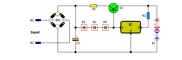
Unlike many units, this battery charger continuously charges at maximum current, tapering off only near full battery voltage. In this unit, the full load. This battery charger is designed to operate with a continuous charging mechanism, maintaining the maximum current...
The PPI-8255 is a general-purpose I/O programmable interface that is typically connected directly to a computer bus. This article demonstrates that the card can serve dual purposes: as an expander port and for direct I/O functionality. The card can...
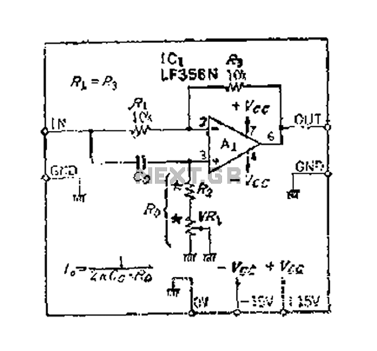
An accurate phase shift of 90 degrees can be achieved using a variable resistor (VR) and an operational amplifier (op-amp). The adjustment allows for a specific frequency to be manipulated. The phase shift can range from 180 degrees to...

An audio power amplifier circuit for a 3-watt stereo amplifier using the MAX 7910 IC is explained below. The audio power amplifier circuit utilizing the MAX 7910 IC is designed to deliver a maximum output power of 3 watts per...
The modular Portable Mixer design featured on these web pages has gained popularity among many amateurs; however, some users have requested a simpler device primarily for mixing mono signals. This design aims to meet those requirements, incorporating three inputs...
This is an electric thermometer circuit composed of the LM134. In the circuit, the voltage or current output by the LM134 is proportional to the thermodynamic temperature, which can be read on a 100 µA meter. The test temperature...
Warning: include(partials/cookie-banner.php): Failed to open stream: Permission denied in /var/www/html/nextgr/view-circuit.php on line 713
Warning: include(): Failed opening 'partials/cookie-banner.php' for inclusion (include_path='.:/usr/share/php') in /var/www/html/nextgr/view-circuit.php on line 713