
Bistable circuit at the operating frequency of 10kHz or less

A bistable circuit, also known as a flip-flop, is a fundamental building block in digital electronics. It has two stable states and can store one bit of data. The circuit can be triggered to switch between these states using input signals. In this case, the bistable circuit is designed to operate at a frequency of 10 kHz or lower, making it suitable for applications that require low-speed data processing and control.
The bistable circuit typically consists of two main components: the input stage and the output stage. The input stage accepts control signals, which can be in the form of clock pulses or other digital signals. These input signals determine the state transitions of the circuit. The output stage provides the stored data, which reflects the current state of the bistable circuit.
Common implementations of bistable circuits include SR (Set-Reset) flip-flops, JK flip-flops, and D (Data) flip-flops. Each type has distinct characteristics and applications. For instance, the SR flip-flop is triggered by the set and reset inputs, while the JK flip-flop allows for toggling between states based on the clock signal. The D flip-flop captures the value of the input signal at the moment of the clock edge, making it ideal for data storage.
In practical applications, bistable circuits are utilized in memory storage, digital counters, and control systems. The ability to operate at frequencies of 10 kHz or lower ensures compatibility with various low-speed digital systems, enhancing reliability and performance in applications such as timers, state machines, and simple data latches. Proper design considerations, including component selection and power supply stability, are essential to ensure optimal functioning of the bistable circuit in its intended application. Bistable circuit at the operating frequency of 10kHz or less
Related Circuits
This post presents an interesting topic about switching power supply circuit diagrams for those who wish to learn more. A switching power supply is a type of power supply that uses a switching regulator to convert electrical power efficiently. Unlike...
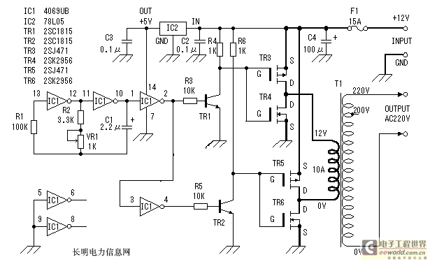
An inverter is introduced which primarily utilizes a MOS field-effect transistor in conjunction with a conventional power transformer. The output power of the inverter is determined by the specifications of both the MOS field-effect transistor and the transformer, thereby...
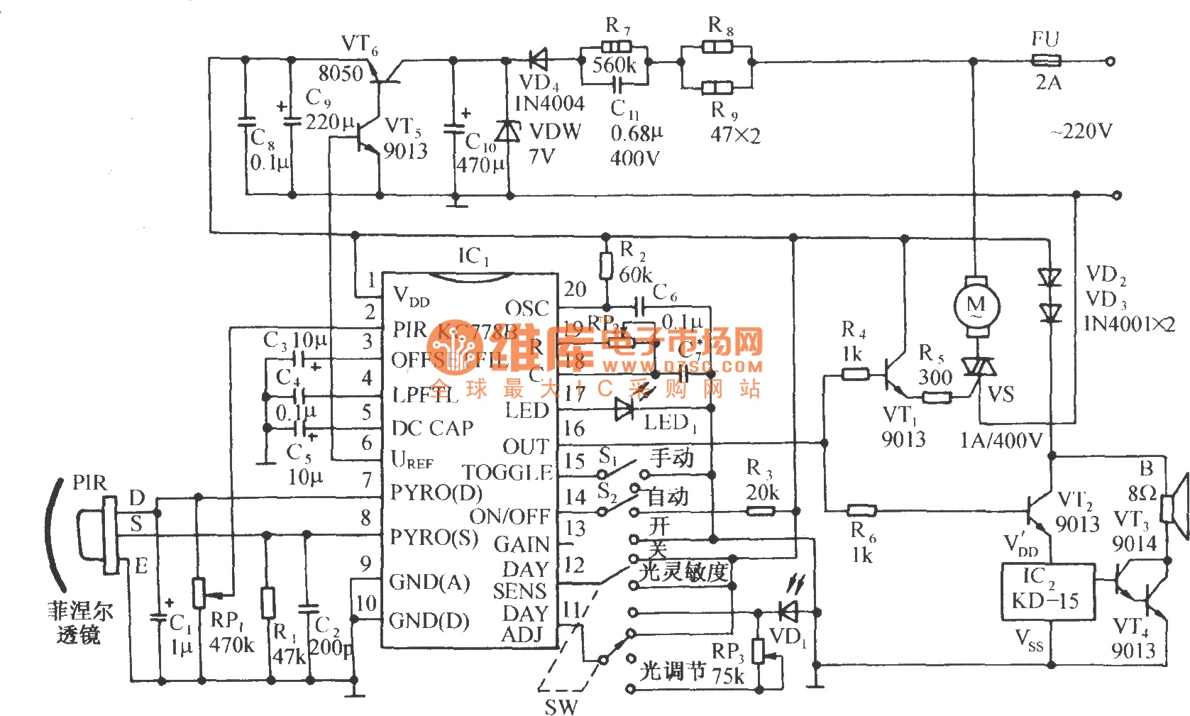
The circuit is depicted in the diagram. It is a control circuit that consists of the infrared-specific integrated circuit KC778B, which serves as the central component. Surrounding it are a pyroelectric infrared sensor head (PIR), a light control and...

This circuit is designed for general-purpose use with a large LED display utilizing SPI serial interfacing. It employs a serial-in-parallel-out shift register, specifically the 74HC595, to receive serial data from a microcontroller board. The schematic wiring indicates that SER...

The circuit utilizes a 555 timer IC to create a lighting group delay effect, as illustrated in Figure 2-46. It consists of the 555 IC along with a resistor and capacitor configuration that establishes the delay. The circuit remains...
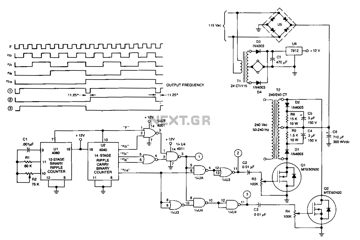
U1 is a 4060 12-stage binary ripple counter that operates as a free-running oscillator, with its frequency of oscillation calculated as 1/2.2 CIR2. The output from U1 is fed into U2, a 14-stage binary ripple counter that generates square-wave...