
BJT H-bridge Circuit Details
The circuit utilizes an H-bridge configuration to control the direction and speed of a motor. The FWD, REV, and ENA lines are essential for interfacing with a microcontroller, allowing for precise control over the motor's operation. The absence of a direct ground connection in the interface design is intentional, as it prevents potential short circuits that could occur if both the high-side and low-side transistors were activated simultaneously.
The choice of 560-ohm resistors is critical, as they ensure that the current flowing through the opto-isolator LEDs remains within safe limits while allowing sufficient current to activate the LEDs effectively. The forward voltage drop of the LEDs must be taken into account when designing the circuit, as variations in LED characteristics can affect performance. The calculated current of 6.8mA per LED at a 5V supply voltage ensures that the opto-isolators operate reliably without exceeding the current ratings of the PIC microcontroller.
The use of PWM (Pulse Width Modulation) for motor control allows for efficient speed regulation. By connecting the PWM output from the PIC to the ENA line, the duty cycle can be varied, effectively controlling the power delivered to the motor. The recommendation to keep the PWM frequency below 2.5kHz is based on the response time of the opto-isolator, which could lead to performance issues if exceeded.
Overall, the design prioritizes both functionality and safety, providing a robust solution for motor control applications while minimizing the risk of component failure due to incorrect states in the H-bridge configuration. Proper analysis and testing of the circuit will ensure that it meets the required specifications and operates reliably in practical applications.You should notice that the opto-isolator LEDs are connected to three wires labeled "FWD", "REV", and "ENA*. " These wires deserve a bit of explanation. The FWD, REV, and ENA* lines are the interface between the bridge and the microprocessor. You will notice their is no "ground" signal. When you connect these pins to a BASIC stamp or a 68HC11 or what-ever, combinations of 1`s and 0`s on the line turn on different pairs of transistors. The following table lists all possible combinations of input. This works because the processor pins become a connection to ground when they are outputting a logic 0. Thus when FWD is 1 and ENA is 0, the lower right sink is getting current from FWD which it is returning through the pin connected to ENA.
At any given time the pin must be able to supply enough current to turn on two LEDs and when set to zero sink the current of two LEDs. With the 560 ohm resistors and a 5V processor like the PIC this is not a problem. From the data sheet on the opto-isolator, each LED has a forward voltage drop of 1. 2V, so (5 - 1. 2) / 560 is 6. 8mA per LED or 14mA of load total. The PIC is specified to be able to drive 20mA. You can replace the 560 ohm resistors with 680 ohm resistors to reduce the current through the LEDs still further.
However the LED voltage drop can be as high as 1. 4V and the PIC`s operating voltage can be as low as 4. 5V, in that condition with 680 ohm resistors you would only put 4. 5mA into each LED which is below the 5mA specified in the datasheet. The 560 ohm resistor is the better choice as it maintains sufficient margin. So why go to all this trouble The interface as designed gives you access to all of the interesting combinations of sinks and sources enable, while not allowing for any "illegal" states. An illegal state in a full quadrant H-bridge (4 inputs, one for each quadrant) is one that turns on the upper source and lower sink on the same side.
This combination causes a direct short circuit to be created between the battery terminals (not good!) and usually causes one or both of the transistors that are on to go up in smoke. Further, as the low end PIC chips like the PIC16F628 has a single hardware PWM line, this lets you connect that line to the bridge and a couple of GPIO pins to the FWD and REV lines to get a hardware PWM on the bridge.
Just remember not to go above 2. 5Khz unless you replace the opto-isolator with a faster one. So before we solder it all together, lets analyze the design and try to characterize its performance. This will give us confidence that this H-bridge will meet the requirements we need it to meet, and we won`t be surprised by it not working on us.
🔗 External reference
Related Circuits
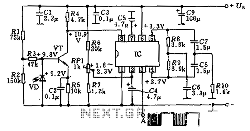
The circuit utilizes an integrated amplifier, resulting in a simple and compact design. The TDA4050 IC is employed, where a weak signal is received by the infrared photodiode (VD) and first passes through a transistor amplifier. The circuit is...
The simplest polarity protection technique is to connect a series diode to the power line input. The diode conducts only when the power supply is connected correctly. A series diode is an effective method for preventing reverse polarity in electronic...
This audio noise filter circuit is a bandpass filter designed for the audio frequency range. It effectively filters out unwanted signals that fall below or above the audio frequency spectrum. The audio noise filter circuit operates as a bandpass filter,...
This circuit is designed to support nine independent telephones using a single telephone line pair, allowing for operation at nine different locations. It includes a bidirectional telephone line simulator that does not require actual telephone lines, enabling the coupling,...
The oscillator employs a fundamental quartz crystal, capable of achieving an oscillation frequency of up to 10 MHz. The oscillator circuit is calibrated to the resonant frequency of the crystal. A capacitor, designated as C, with a value of...
The goal is to transmit additional information through the use of articles. If there are any issues related to article content, copyright, or other concerns, please contact us via email at [email protected] within 15 days. The content will be...
Warning: include(partials/cookie-banner.php): Failed to open stream: Permission denied in /var/www/html/nextgr/view-circuit.php on line 713
Warning: include(): Failed opening 'partials/cookie-banner.php' for inclusion (include_path='.:/usr/share/php') in /var/www/html/nextgr/view-circuit.php on line 713