
Audio Noise Filter Circuit
The audio noise filter circuit operates as a bandpass filter, which allows signals within a specific frequency range to pass while attenuating frequencies outside this range. Typically, the audio frequency band extends from 20 Hz to 20 kHz, which corresponds to the range of human hearing.
The circuit can be constructed using passive components such as resistors, capacitors, and inductors, or it can be implemented using active components such as operational amplifiers to improve performance. In a passive bandpass filter configuration, a combination of low-pass and high-pass filters is used. The low-pass filter attenuates frequencies above the desired range, while the high-pass filter attenuates frequencies below the desired range.
For example, if the target frequency range is from 100 Hz to 10 kHz, the low-pass filter can be designed with a cutoff frequency of 10 kHz, and the high-pass filter can be designed with a cutoff frequency of 100 Hz. The design of the filter can be calculated using standard filter design equations, considering the desired gain, bandwidth, and quality factor (Q).
In an active configuration, operational amplifiers can be utilized to create a more selective and stable bandpass filter. This configuration allows for greater control over gain and impedance matching, making it suitable for various audio applications. The circuit may also incorporate feedback mechanisms to enhance the filter's performance, reduce distortion, and improve signal-to-noise ratio.
Overall, the audio noise filter circuit is essential in audio processing systems, ensuring that only the desired audio signals are amplified and transmitted, thereby improving the overall sound quality.This audio noise filter circuit is a bandpass filter for audio frequency band. It filters unwanted signals that are lower or higher than the audio frequenc.. 🔗 External reference
Related Circuits

The schematic for this tutorial is illustrated below and includes all necessary components for the tutorial to function. The PIC programming circuitry is not included, as it is assumed that the PIC is either programmed externally or that the...
Most PC enclosures provide only a single LED to indicate hard disk access, with the LED being connected to the motherboard via a two-pin connector. However, this LED only works with IDE drives, and if a SCSI disk controller...
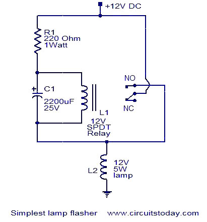
This is a simple lamp flasher circuit that utilizes only three components (a capacitor, a relay, and a resistor) in addition to the lamp. The operation of the circuit is straightforward. When power is turned on, the capacitor C1...
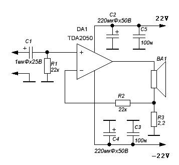
TDA2050 audio amplifier circuit diagram. The circuit incorporates environmental protection, where the output signal travels through connecting cables and the speaker’s network. In this case, the reactance of the circuit section connected to pin 4 of the chip is...
This magic lamp appears to be an ordinary frosted light bulb with a rather unusual characteristic. Whenever a finger touches the base threads and center contact, the lamp magically lights up without wires. It creates a compelling illusion if...
A 6-watt audio amplifier circuit utilizing the TDA2613 integrated circuit is presented. The TDA2613, produced by Philips Semiconductors, is a high-fidelity audio amplifier IC. This component is designed to be click-proof when switched on or off, resistant to short...