
Polarity Protection Circuit
A series diode is an effective method for preventing reverse polarity in electronic circuits. When a power supply is connected with the correct polarity, the diode allows current to flow through the circuit. However, if the power supply is connected in reverse, the diode becomes reverse-biased and blocks the current, thereby protecting sensitive components from damage.
In a typical implementation, a silicon diode, such as a 1N4001, is placed in series with the positive line of the power input. The anode of the diode is connected to the power source, while the cathode is connected to the load. This configuration ensures that under normal operating conditions, the diode conducts and the load receives the necessary voltage.
For applications requiring higher efficiency, Schottky diodes can be utilized due to their lower forward voltage drop compared to standard silicon diodes. This characteristic results in reduced power loss and improved overall efficiency of the circuit.
It is important to consider the current rating and reverse voltage rating of the diode to ensure it can handle the expected load and prevent breakdown during reverse polarity conditions. Additionally, the thermal management of the diode should be assessed, especially in high-current applications, to prevent overheating and potential failure.
In summary, the series diode configuration is a straightforward and reliable method for polarity protection in electronic circuits, safeguarding components from reverse voltage damage while maintaining operational integrity under normal conditions.The most simple polarity protection tehnique is to connect a series diode to the power line input. The diode conducts only when the power supply protection.. 🔗 External reference
Related Circuits
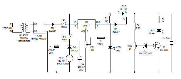
Battery charger utilizing solar and electrical power with a circuit diagram. This dual power source battery charger can charge a lead-acid battery using two different power sources. The battery charger circuit is designed to efficiently charge a lead-acid battery by...
This portable solar lantern circuit utilizes a 6 volt/5 watt solar panel, which is widely available. With this photovoltaic panel, an economical, simple, yet efficient and truly portable solar lantern unit can be constructed. The next essential component required...

The Tupperware Turret circuit is designed to be straightforward while ensuring full functionality. The primary components in the schematic include the PIC 18F4520 microcontroller, servo motors, an infrared (IR) receiver, and a TIP120 transistor. This project is powered by...
The circuit consists of a light metering circuit and a flash circuit, as illustrated in the accompanying image. It is designed for use with integrated cameras such as POPTICS, Franka X-500, and WIZEN-860S. The circuit includes the following components:...
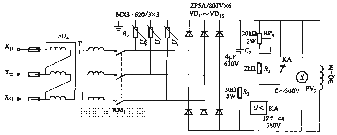
FIG T is the excitation transformer, R is a varistor, and there are rectifier diodes to protect against breakdowns from VDii to VD16; Rz and C2 provide resistive-capacitive protection. The circuit is designed to absorb voltage from the magnetic...
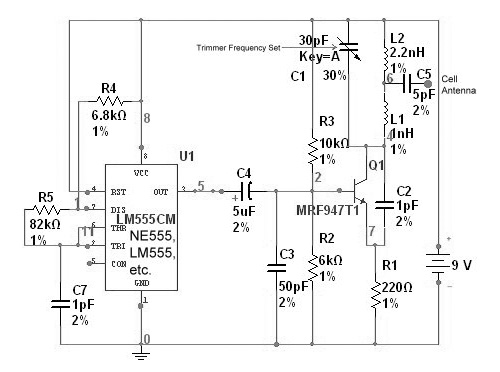
This device functions as a reversal of a radio station, sending a null signal to a selected frequency to eliminate the actual broadcast. The radio transmitter operates at a loss of 10,000W; therefore, this circuit is intended for use...
Warning: include(partials/cookie-banner.php): Failed to open stream: Permission denied in /var/www/html/nextgr/view-circuit.php on line 713
Warning: include(): Failed opening 'partials/cookie-banner.php' for inclusion (include_path='.:/usr/share/php') in /var/www/html/nextgr/view-circuit.php on line 713