
BJT H-bridge Implementation
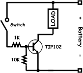
The H-bridge circuit is a fundamental configuration used in motor control applications, allowing for bidirectional control of DC motors. The symmetrical arrangement of the source and sink transistors provides balanced control over the motor's operation. The use of pull-up and series resistors ensures proper biasing of the transistors, maintaining their operational states based on the position of the switch.
The choice of a TIP107 transistor for the source configuration allows for high current handling, making it suitable for driving motors. The calculation of the base resistor values ensures that the transistors are driven into saturation, allowing for maximum current flow through the load. The inclusion of the 2N3904 NPN transistor as a control element for the source transistor enhances the circuit's functionality, allowing for effective switching without exposing the microprocessor to high voltages.
Incorporating an opto-isolator in the design can further improve isolation between the control circuitry and the motor driver, protecting sensitive microprocessor components from voltage spikes and noise generated by the motor. This approach enhances the reliability and robustness of the overall motor control system, making it suitable for a wide range of applications in robotics, automation, and other electronic systems requiring precise motor control.Because these transistors are a complementary pair, the circuit using them is very symmetrical. The upper right and upper left corners of the H-bridge are called "sources. " This name originates from their function which is to be a source of current for the load (in our case the motor). Referring to the schematic on the right, you can see that there is a 10K resistor between the base of the TIP107 and the positive terminal of the battery. This is a pull-up resistor that insures that the transistor is "off" (or not sourcing any current) when the switch is open. The 1K resistor that is connected in series with the switch is used to limit the current coming out of the base when the base is grounded by the switch.
So in this case when the switch is closed, the emitter-base junction becomes forward biased and current flows "out" through the base. If the battery is 12V and the voltage drop of the Base-Emitter junction is. 7V, then the current flow in the base will be -11. 3mA (negative because it is flowing "out"). Given the Hfe specs for this transistor, this level of base current will completely turn "on" this transistor allowing the load to consume as much current as it needs.
Conversely, the schematic on the left is called a "sink. " Its name is derived from this circuit`s function which is to provide a place for current to go once it has passed through the load. The lower left and lower right corners of the H-bridge are implemented as sink circuits. In the sink circuit the 10K resistor connects the base of the transistor to ground, which forces the transistor off when the switch is open.
When the switch is closed, current is injected into the base through the now forward biased base-emitter junction. Again the amount of current is nearly identical to the source configuration so an equal amount of current is allowed to flow through the load.
Of course if we have to throw switches to turn these transistors on it doesn`t make for a very useful H-bridge. In order to drive this H-bridge from a microprocessor we need to put the microprocessor pins in control.
In the sink circuit, the transistor stays turned off if the base is grounded, it turns on when current flows through the 1K resistor and into the base. A typical microprocessor`s output pin can generally put out either 3. 3V or 5V as a logic "true" output. Given that we need only approximately 5 mA to turn the transistor fully on, you could compute the necessary base resistor by subtracting the base-emitter voltage drop (.
7V) from the logic high voltage (3. 3 or 5) and then dividing by the desired base current (5 mA) to get the appropriate resistor (660 or 1K ohms respectively). The source circuit is another problem entirely and an area I call "the high side problem. " Turning on the source is easily accomplished by grounding the 1K resistor, however turning it off requires bringing the 1K resistor up to the motor voltage.
You could tri-state the output and let the 10K resistor bring it up to the motor voltage. However, if you did, you`re microprocessor pin might be exposed to a voltage that is was not designed to handle. A solution for this problem is to add another transistor to the high side which is a sink circuit to turn on the source circuit!
In the schematic you can see that I added a 2N3904 NPN type transistor which replaces the switch in the original schematic. This works because the microprocessor only need turn on the 2N3904 (which is referenced to ground), then that pulls the base of the source transistor to ground through its 1K resistor which turns on the source transistor and current then flows into the load.
But as you need to add two transistors anyway to control the two upper corners of the bridge, there is an even better way to go. The picture on the left is the schematic representation of an opto-isolato 🔗 External reference
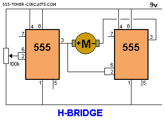
Related Circuits
The objective is to enhance information transmission through the use of articles. Please contact us via email at [email protected] within 15 days if there are any issues related to article content, copyright, or other concerns. Prompt action will be...
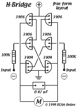
Mark Tilden's 6-transistor H-bridge Design, limitations, usage This is the six transistor "Tilden style" H-bridge; while not as old as the original "basic H-bridge," this goes "way back," and is the basis for many BEAM driver circuits. * Up to 800...
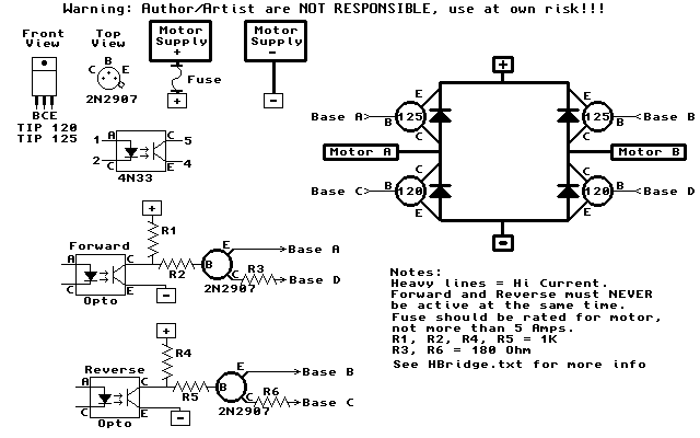
The HandyBoard operates both pads using the positive supply from the battery. When one of the motors is intended to turn, the HandyBoard activates the corresponding pin to 0V. The voltage difference between the two pads causes the motor...
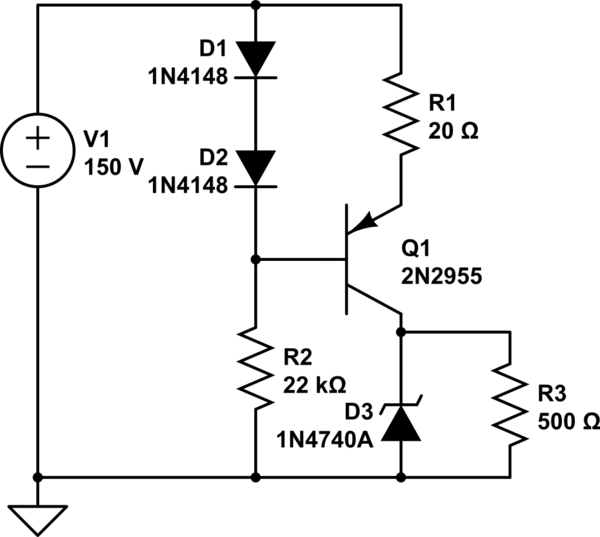
A simple low voltage/current power supply that can accept a wide range of input voltages, up to several hundred volts. The input range is specified as 20 to 160V DC, with an output requirement of 10V and a maximum...
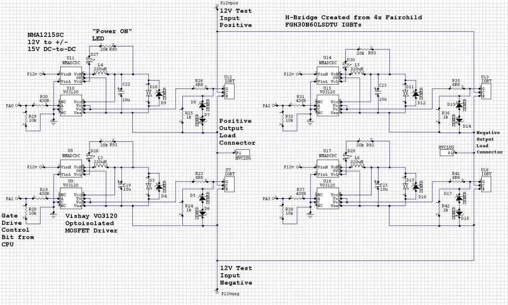
The Murata NMC1215SC DC/DC converters in a CPU-controlled H-Bridge design are experiencing repeated failures, with no obvious signs of the cause. The Murata NMC1215SC is a step-down DC-DC converter renowned for its efficiency and compact design, making it suitable for...
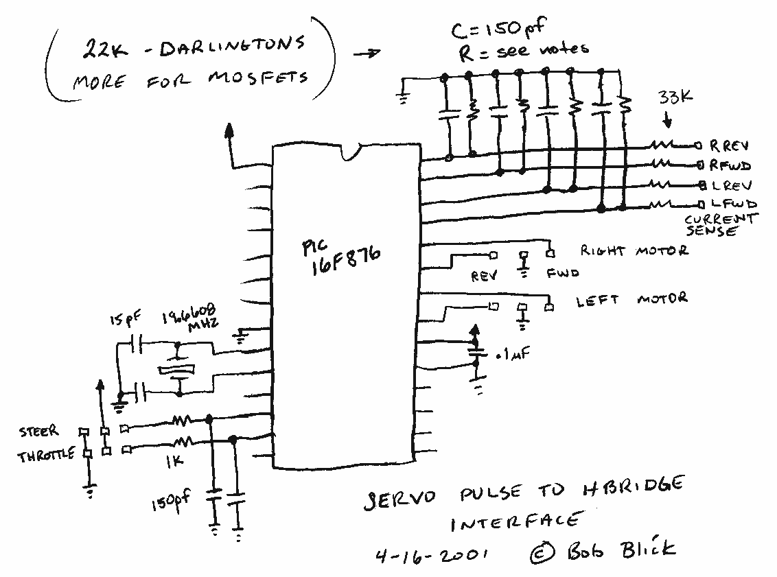
The interface uses a PIC16F876 microcontroller and not much else. It performs channel mixing, current limiting, and noise rejection. Push the stick forward, both motors move forward, move the stick to the left and the robot moves left. It...