
H-Bridge

The HandyBoard circuit utilizes a straightforward control mechanism for motor operation, leveraging the difference in voltage across two pads to facilitate rotation. The circuit includes a pair of TIP120 and TIP125 transistors that function as switches to control the motor's direction by toggling the voltage levels on the pads. When a motor is commanded to turn, the HandyBoard drives the appropriate control pin low (0V), creating a potential difference that energizes the motor.
The transistors are capable of managing a continuous current of 5 mA, necessitating the use of heatsinks to dissipate heat generated during operation. These components must be installed in a top-down configuration to ensure proper attachment of the heatsink, which is critical for maintaining operational efficiency and preventing thermal overload.
Incorporating an IR LED and an IR resistor into the circuit allows for monitoring the status of the fuse. The IR LED emits light that illuminates the IR resistor; when the fuse is functional, the HandyBoard can detect the resulting signal through its analog input. Conversely, a blown fuse results in the IR LED not functioning, causing the IR resistor's resistance to increase significantly. This change in resistance can also be monitored by the HandyBoard, providing an effective means of fuse status detection.
To enhance the performance of the IR components, it is essential to shield them from ambient light, which could interfere with the circuit's operation. This can be achieved through the use of enclosures or strategic placement within the overall design. Proper attention to these details ensures reliable motor control and effective fuse monitoring within the HandyBoard circuit.The HandyBoard drives both pads at the positive supply of the battery. When one of the motor is supposed to turn, the handyboard drives the appropriate pin at 0V. The difference between two pads makes the motor turn. The Transistors are TIP 120 and TIP 125 but could be changed for more recents ones. They are supposed to drive 5 mA continous with a ppropriate HeatSink. They must be soldered TOP DOWN in order to be able to connect a heatsink. The IR Led and IR Resistor should be protected from the ambiant light. When the fuse is OK, the IR Led is illuminating the IR Resistor and the HandyBoard can detect it throught any analog input port. If the fuse is blowed, the IR Led isn`t working and the IR Resistor increases it`s resistance and this can be detected by the HandyBoard.
🔗 External reference
Related Circuits
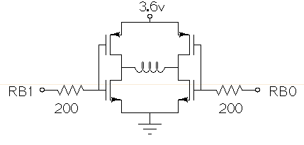
Drive a small (3.6V, <1A) brushed motor bidirectionally with a PIC microcontroller (MCU). The available space is extremely limited, so a single 3.6V power supply will be used for both the motor and the PIC, with minimal drive circuitry required. There is no dedicated motor driver IC that operates at this low voltage, making a discrete H-bridge the most suitable drive arrangement. The NXP PMV30UN and PMV32UP have been identified as suitable N-type and P-type drive MOSFETs. Since both the PIC and the motor share the same power supply, it is questioned whether it is possible to eliminate the usual driving circuitry for an H-bridge and connect the transistors directly to the MCU pins. Potential pitfalls of this approach should also be considered. To design a bidirectional motor drive circuit using a PIC microcontroller and a discrete H-bridge configuration, the following considerations must be taken into account. The H-bridge consists of four MOSFETs arranged in a configuration that allows current to flow through the motor in either direction, enabling bidirectional control. The NXP PMV30UN and PMV32UP MOSFETs are suitable candidates due to their low on-resistance and capability to operate at the required 3.6V supply voltage. The connections between the PIC MCU and the MOSFETs should be made with consideration of the gate drive requirements. Directly connecting the MOSFET gates to the MCU pins can be feasible, but it is essential to ensure that the MCU can provide sufficient gate drive voltage to fully turn on the MOSFETs. A typical threshold voltage for these MOSFETs is around 1V, so the output high level from the PIC should exceed this threshold to ensure efficient operation. It is also critical to incorporate pull-down resistors on the gate pins to prevent the MOSFETs from floating when the MCU is in a high-impedance state. This will help avoid unintended motor activation. Additionally, using gate resistors can help dampen any oscillations and limit inrush current during switching, which could potentially damage the MOSFETs or the MCU. Another consideration is the back EMF generated by the motor when it is switched off or when changing direction. This can induce voltage spikes that may damage the MCU or the MOSFETs. To mitigate this risk, flyback diodes should be placed in parallel with each MOSFET to provide a path for the back EMF, ensuring safe operation of the circuit. Thermal management is also a critical aspect of the design. Although the MOSFETs are rated for low on-resistance, continuous operation near their current limits can lead to significant heat generation. Adequate heat dissipation measures, such as heat sinks or thermal pads, should be considered. In summary, while it is possible to connect the MOSFETs directly to the MCU pins, careful attention must be given to gate drive requirements, protection against back EMF, and thermal management to ensure reliable and efficient operation of the bidirectional motor drive circuit.
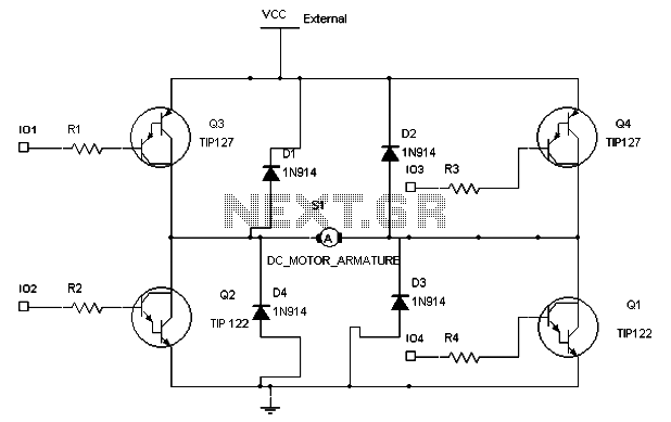
To maintain a constant speed of the motor under varying load conditions, a control application circuit is required. An H-Bridge circuit can be utilized to manage both the speed and direction of the motor. The accompanying diagram illustrates the...
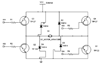
The diagram below illustrates an H-Bridge circuit featuring four inputs and an external power supply. The control application must enable the motor to operate in both forward and reverse directions. The H-Bridge is a crucial component in motor control applications,...
This H-bridge variant was one of the first in which the reversing circuitry is built into the driver, rather than (as is more-commonly done) into the control circuitry upstream of the driver. This is a handy circuit, though, for...
It was previously assumed that dynamic braking would be most effective at higher speeds. However, tests conducted with a Faulhaber (Micro Mo) gear motor demonstrated that the brake could hold the motor almost stationary. These gear motors are constructed...
The circuit employs a complementary pair of transistors, resulting in a symmetrical design for the H-bridge configuration. The upper corners of the H-bridge are referred to as "sources," indicating their role in supplying current to the load, which in...