
Dual Channel Servo Pulse to H-Bridge Interface

The described robotic interface utilizes the PIC16F876 microcontroller, which serves as the central processing unit for managing the control signals and motor operations. The microcontroller is responsible for interpreting input from a wheel transmitter, typically used for RC cars, allowing for intuitive control over the robot's movement. The system features two primary functions: channel mixing and current limiting, which enhance the robot's maneuverability and safety.
Channel mixing is implemented to ensure that both motors respond appropriately to the control stick's position. When the stick is pushed forward, the microcontroller sends signals to both motors to operate in the forward direction, enabling straight-line movement. Conversely, when the stick is moved left, the microcontroller adjusts the speed of each motor accordingly, allowing the robot to turn left smoothly. This feature significantly improves the driveability of the robot, making it easier to navigate various terrains.
The current limiting function is crucial for protecting the H-Bridge transistors, which are used to control the direction and speed of the motors. The system incorporates cycle-by-cycle current sensing, which monitors the current flowing through the transistors. If an over-current condition is detected, the microcontroller can take corrective action to prevent damage, ensuring the longevity and reliability of the robotic system.
Noise rejection is another essential aspect of the design. The microcontroller is programmed to filter out any extraneous signals from the receiver, whether the transmitter is active or inactive. This capability ensures that the robot operates smoothly without interference from unwanted noise, which could lead to erratic movements.
Additionally, the design allows for the potential incorporation of temperature sensing. While this feature has not been implemented in the current version, it could provide valuable feedback for monitoring the operating conditions of the motors or the microcontroller itself, enhancing the overall functionality of the robotic system.
In summary, the interface developed around the PIC16F876 microcontroller effectively combines channel mixing, current limiting, and noise rejection to create a robust control system for a robotic platform. The design allows for intuitive control via a wheel transmitter, ensuring smooth and responsive operation in various driving scenarios.The interface uses a PIC16F876 microcontroller and not much else. It performs channel mixing, current limiting, and noise rejection. Push the stick forward, both motors move forward, move the stick to the left and the robot moves left. It makes the robot very driveable. You can use a wheel transmitter meant for cars to control it, in other words, one channel is throttle(both forward and reverse), the other steering.
Speed control is smooth, and the H-Bridge transistors are sensed and protected cycle-by-cycle against over-current. Noise from the receiver, whether the transmitter is on or off, is ignored. Temperature sensing is also possible, but I havent incorporated it in this version. 🔗 External reference
Related Circuits
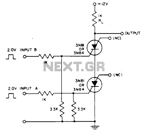
Voltage across resistor Rl is only present when inputs A and (2- to 3-V amplitude) occur simultaneously. A brief overlap of less than 1 microsecond is enough to trigger the silicon-controlled switch (SCS). Coincidence of negative inputs is detected...
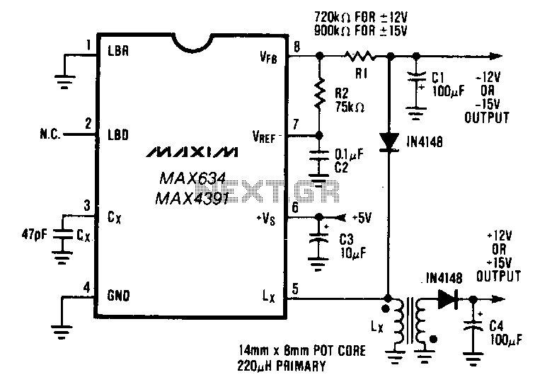
The buck-boost configuration of the MAX634 is well suited for dual output DC-DC converters. Only a second winding on the inductor is needed. Typically, this second winding is bifilar; the primary and secondary are wound simultaneously using two wires...

The objective is to vary two voltages, V1 and V2, by an equal percentage of their respective ranges (V1MAX - V1MIN and V2MAX - V2MIN), where V1MAX, V1MIN, V2MAX, and V2MIN are independent of one another. A common approach...

The 040904C version of the code has a larger UART receive buffer and supports two pushbuttons that send either an ASCII "R" ($52) or an ASCII carriage. Something to keep in mind when using AVR controllers that support 16-bit...

A peculiar issue has arisen over the past few months regarding the stock muffler flaps and valves, which are not opening at any RPM, including above 3500 RPM. They do not appear to be stuck, as they operate correctly...
Circuit to control RC servos using 0-10V control voltage This circuit is designed to control RC servos by utilizing a control voltage range of 0 to 10 volts. The operation of the circuit is based on the principle of converting...