
bjt transistor circuit finding the resistances
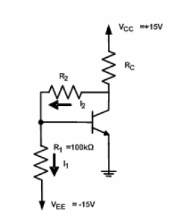
For resistors R1 and R2, which create a voltage divider spanning from -15V to +5V, it is necessary to configure them such that the top of R1 reaches 0.7V (VBE). The voltage divider thus spans a total of 20V, with the 0.7V base voltage being 15.7V above the lower end of the voltage divider. It is important to note that the base current can be considered negligible in many transistor circuit analyses; however, due to the high resistance of R1, this assumption may not hold. The base current, calculated as 2mA divided by β, amounts to 0.02mA or 20µA. To find the current flowing through R1, one must consider its resistance and the voltage of 15.7V across it. The current through R2 is the total of the base current (0.02mA) and the current through R1. With the current through R2 and the voltage across it known, the resistance of R2 can be determined.
The circuit analysis begins with the identification of the required parameters for the transistors in use. The collector current (IC) is set at 2mA, which indicates the operational state of the transistor. The collector-emitter voltage (VCE) is specified as 5V, which is critical for determining the voltage drop across the collector resistor (RC). The calculation of RC is straightforward: with a voltage drop of 10V across it (the difference between the supply voltage and VCE), the resistance can be derived using Ohm’s law.
Next, the voltage divider formed by R1 and R2 must be correctly configured to ensure the base of the transistor is biased at 0.7V. The voltage divider's total voltage range is 20V, spanning from -15V to +5V. The voltage at the top of R1, which should be at 0.7V, indicates that the voltage divider must be appropriately designed to achieve this biasing condition.
Given that R1 has a high resistance value, the base current (IB) cannot be neglected in this analysis. The base current, which is a function of the collector current and the transistor's current gain (β), is calculated as 20µA. This current flows through R1, and the total current through R2 will be the sum of the base current and the current flowing through R1.
To finalize the calculations, the current through R1 needs to be determined based on its resistance and the voltage across it. Subsequently, the total current through R2 can be calculated, allowing for the determination of R2's resistance using Ohm's law, as the voltage across R2 is known. This comprehensive analysis ensures that both resistors are accurately calculated for the desired operation of the transistor circuit.I have been given the following circuit diagram and have been asked to compute R2 and RC such that, at the Q-point, the circuit will behave as follows: VCE=5V VBE=0.7V IC=2mA β=100(where β=ic/ib) There are many places we can begin looking at this. We know that the collector current is 2 mA, and that VCE is 5V. Since the emitter is at ground, the collector must be at 5V, and so the voltage across RC is therefore 10V: the difference between 5V and 15V. So RC must be 10V/.002A=5KΩ. Next, R2 and R1 which span a voltage from −15V to +5V must form a voltage divider such that the top of R1 is at 0.7V (VBE).
Hint: the voltage divider spans a range of 20V, and the 0.7V transistor base voltage is 15.7V above the bottom of the voltage divider. This approach assumes that we can ignore the base current because it is small. Often when analyzing transistor circuits we can do that, but not in this case because R1 is such a high resistor.
The voltage divider is not "stiff" at all with regard to the resistance in the base circuit of the transistor (which has no emitter resistor at all). A more exact answer requires that we account for the base current. The transistor is carrying only 2mA of current, and so is nowhere near hard saturation, and so the base current is only 0.02 mA, or 20 micro-Amperes (2mA divided by β).
Determine how much current is flowing through R1 from its resistance, and 15.7 voltage. The current flowing through R2 is the sum of the transistor base current (.02 mA) and the current through R1. Knowing the current through R2 and the voltage across it, we can calculate its resistance. 🔗 External reference
Related Circuits
The remote control robot circuit is illustrated in the accompanying figure. Figure 2-36(a) presents the circuit diagram, while figure 2-36(b) depicts the operating timing diagram. The robot's rotation process involves an ultrasonic launching circuit, which consists of a 40...
This touch-on switch can be activated through electrical means and can only be reset using a mechanical switch. When the touch terminal is activated by a finger, the SCR turns on and illuminates LED1. The circuit utilizes a silicon-controlled rectifier...
The circuit principle involves an oxygen sensor circuit utilizing the OS-12, a DC amplifier IC1, an A/D converter IC4, a liquid crystal display F2100-34PI, a voltage comparator IC2, and a positive and negative power converter IC, among other components....
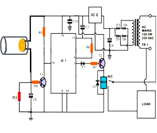
The following post illustrates a simple light-operated remote control circuit that can be activated by an ordinary flashlight or, more effectively, through a laser beam unit (keychain type). The Light Dependent Resistor (LDR) is connected between the base of...
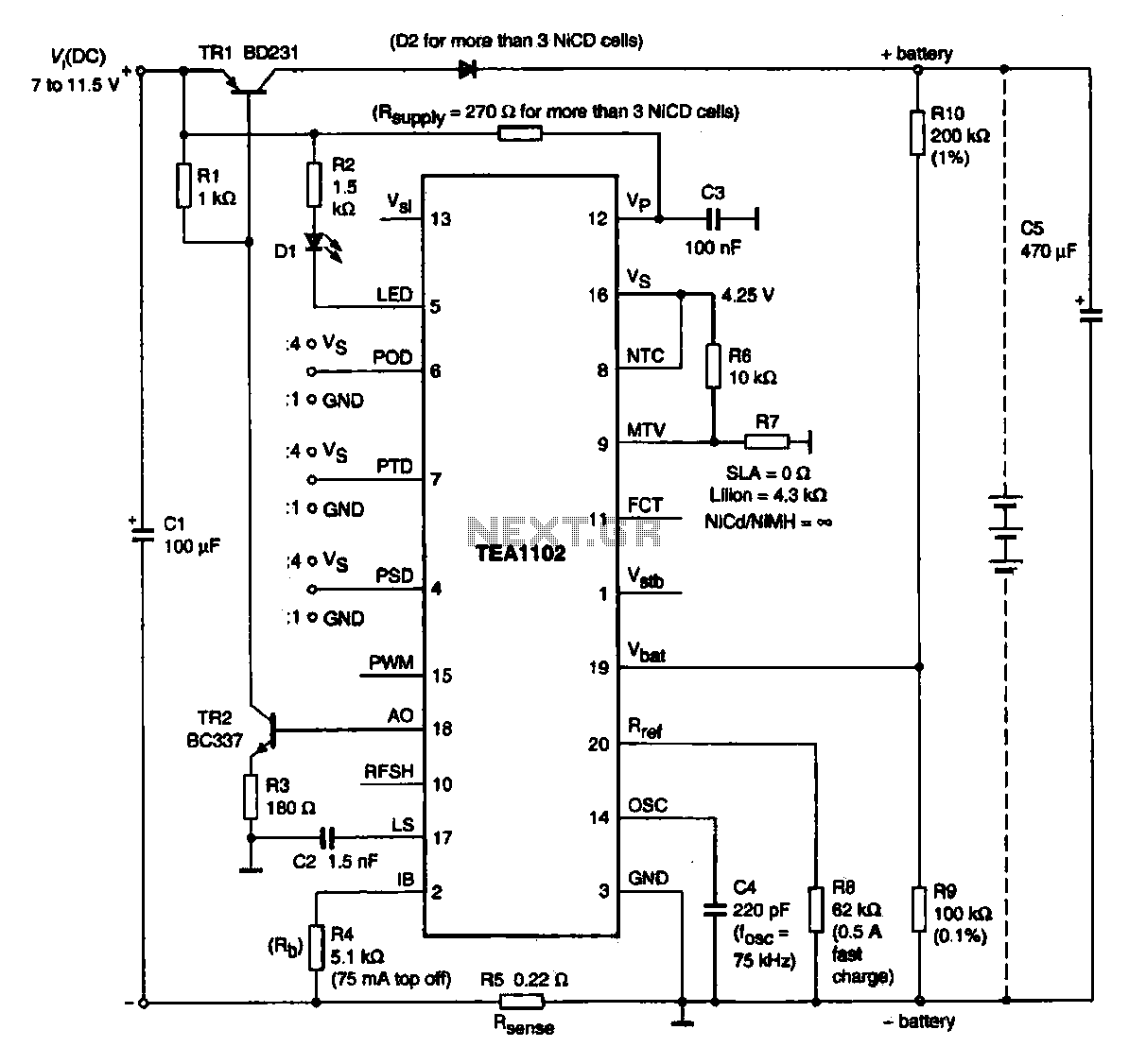
A fast charging circuit utilizing the TEA1102 controller is designed for various battery types. This circuit operates with a DC power supply voltage ranging from 7 V to 11.5 V and is compatible with nickel-cadmium, nickel-hydrogen, and lithium-ion batteries. The...
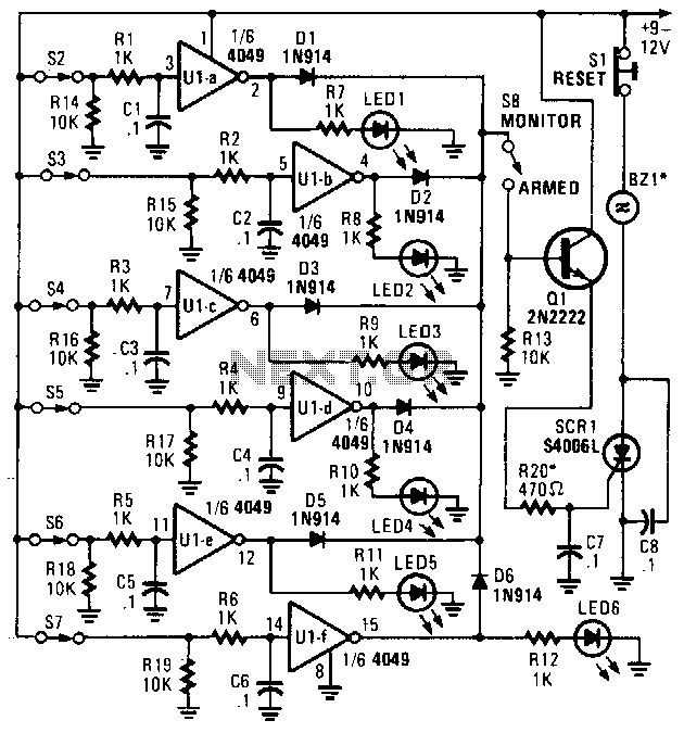
This alarm features status LEDs connected to each inverter output, which indicate the status of the corresponding sensor. S8 is utilized to monitor the switches through the LEDs or to activate an alarm using Q1 and SCR1. Additionally, BZ1...
Warning: include(partials/cookie-banner.php): Failed to open stream: Permission denied in /var/www/html/nextgr/view-circuit.php on line 713
Warning: include(): Failed opening 'partials/cookie-banner.php' for inclusion (include_path='.:/usr/share/php') in /var/www/html/nextgr/view-circuit.php on line 713