
Remote control robot circuit
The remote control robot circuit operates based on ultrasonic wave detection and response. The primary components include an ultrasonic transmitter and two receivers positioned strategically to detect the reflected ultrasonic waves. The circuit diagram in Figure 2-36(a) outlines the configuration of the oscillating circuit, which generates a 40 kHz signal, and the driving circuit that powers the ultrasonic transmitter.
The ultrasonic transmitter emits sound waves that travel through the air and reflect off nearby objects. The two sensors, typically arranged at specific angles, detect these reflected waves. The time taken for the waves to return to the sensors is measured to determine the distance to the nearest obstacle. This information is crucial for the robot's navigation and obstacle avoidance capabilities.
The operating timing diagram in Figure 2-36(b) illustrates the sequence of events during the robot's operation. It shows the timing for the transmission of ultrasonic pulses and the subsequent reception of echoes by the sensors. The timing is critical to ensure accurate distance measurement and effective control of the robot's movements.
In summary, the remote control robot circuit leverages ultrasonic technology for navigation, utilizing a combination of oscillating and driving circuits along with strategically placed sensors to facilitate obstacle detection and response. This design allows for efficient operation and maneuverability in various environments.The remote control robot circuit is as shown in the figure. The figure 2-36(a) is the circuit diagram, the figure 2-36(b) is the operating timing diagram. The rotation process of the rebot is: in the circuit, the ultrasonic launching circuit is composed of the 40kHz oscillating circuit and driving circuit. The two sensors receive the ultrasonic wave: one rec.. 🔗 External reference
Related Circuits
The PWM circuit is causing the inverter's current consumption to reach a dangerous level of 14 Amps. A potential solution involves reducing the drive voltage to the gates of the MOSFETs by controlling the base voltage of the buffer...
This simple microcontroller circuit regulates a servo motor based on a 3-state switch. The servo motor functions as an actuator with three positions. It consists of three wires: one for VCC, one for ground, and a third for position...
The application circuit operates as depicted below. It typically utilizes a shared TV antenna amplifier and an isolated power switch for the user. There are instances when the TV may not function, yet the antenna amplifier remains powered, leading...
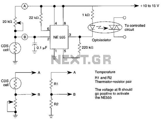
This dark-activated relay switch can be utilized to activate walkway or other outdoor lighting at dusk. By employing alternate connections to points A and B, it is capable of sensing varying levels of illumination, as well as high and...
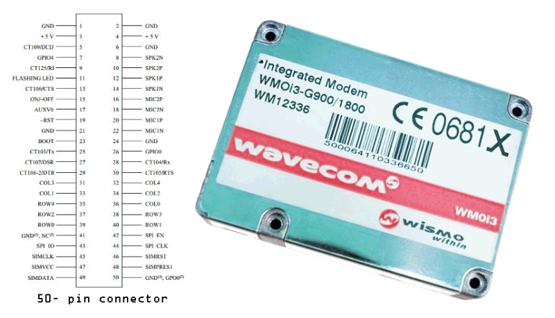
Modems are devices that connect remote devices to a computer or enable communication between multiple computers. While traditional modems typically use wired connections, the GSM modem described here operates wirelessly. It can link two computers, connect a computer to...
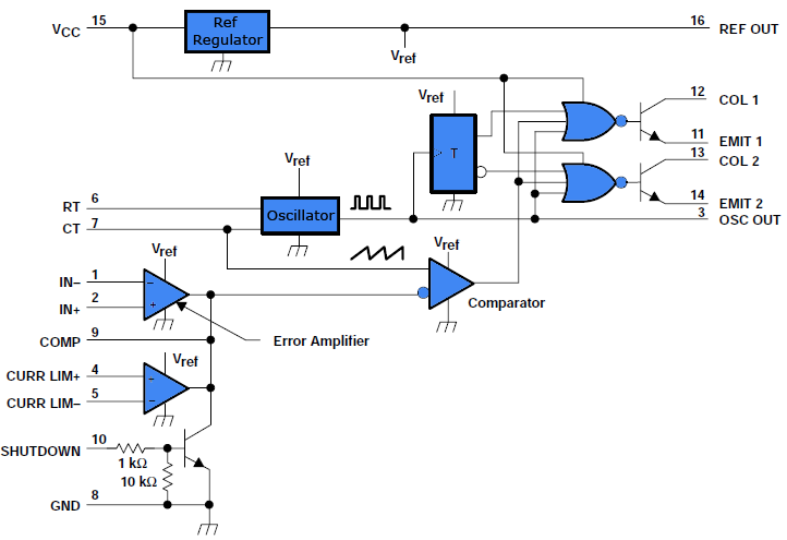
This document outlines a simple PWM (Pulse Width Modulation) DC to AC voltage inverter circuit based on the SG3524 integrated circuit. The SG3524 is a fixed frequency PWM voltage regulator control circuit that offers indifferent outputs suitable for both...