
Black Light
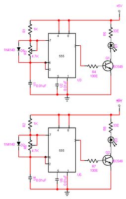
The described circuit utilizes a 6-volt power source, which can be either a battery or a power supply capable of delivering a current of 1 amp or more. The primary component responsible for generating ultraviolet (UV) light is typically a UV LED or a UV lamp.
In a basic configuration, the circuit may include a resistor in series with the UV light source to limit the current and prevent damage to the LED or lamp. The value of the resistor can be calculated using Ohm’s law, taking into account the forward voltage drop of the UV LED or lamp and the desired operating current.
For instance, if a UV LED has a forward voltage of 3.2 volts and a desired current of 20 mA, the required resistor value can be determined as follows:
1. Calculate the voltage drop across the resistor:
Voltage drop = Source voltage - Forward voltage = 6V - 3.2V = 2.8V.
2. Use Ohm's law (V = IR) to find the resistance:
R = Voltage drop / Desired current = 2.8V / 0.02A = 140 ohms.
In practice, a standard resistor value of 150 ohms could be used, which would slightly reduce the current but still allow the LED to operate efficiently.
The circuit may also include a switch to control the operation of the UV light, and possibly a fuse for safety, ensuring that the circuit is protected against overcurrent conditions. Additionally, a heat sink may be necessary if a higher power UV lamp is used, to dissipate heat and maintain optimal operating conditions.
Overall, this simple ultraviolet light circuit can be applied in various applications, including sterilization, curing of UV-sensitive materials, or as a light source for specific scientific experiments. Proper safety measures should be considered when working with ultraviolet light, as it can be harmful to skin and eyes.This circuit is a simple ultraviolate light that can be powered by a 6 volt battery or power supply (such as the power supply on the "Circuits" page) that is capable of supplying 1 or more amps. 🔗 External reference
Related Circuits
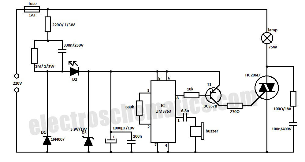
This whistle light switch allows for the control of lighting installations. The primary component of this circuit is the UM3763 integrated circuit, manufactured by UMC. A piezo-ceramic buzzer serves as a microphone, detecting sound frequencies between 1.2 kHz and...
High-energy capacitors can produce hundreds of amps when short-circuited, potentially causing severe burns, fires, and property damage. It is essential to be aware of these hazards when using such capacitors and to take precautions to avoid accidental short-circuits. The...
As a cyclist, there is a constant search for methods to enhance visibility during nighttime rides. The concept of the `NITE-RIDER` was developed to create a distinctive and attention-grabbing rear light for bicycles. This design features nine extra-bright LEDs...
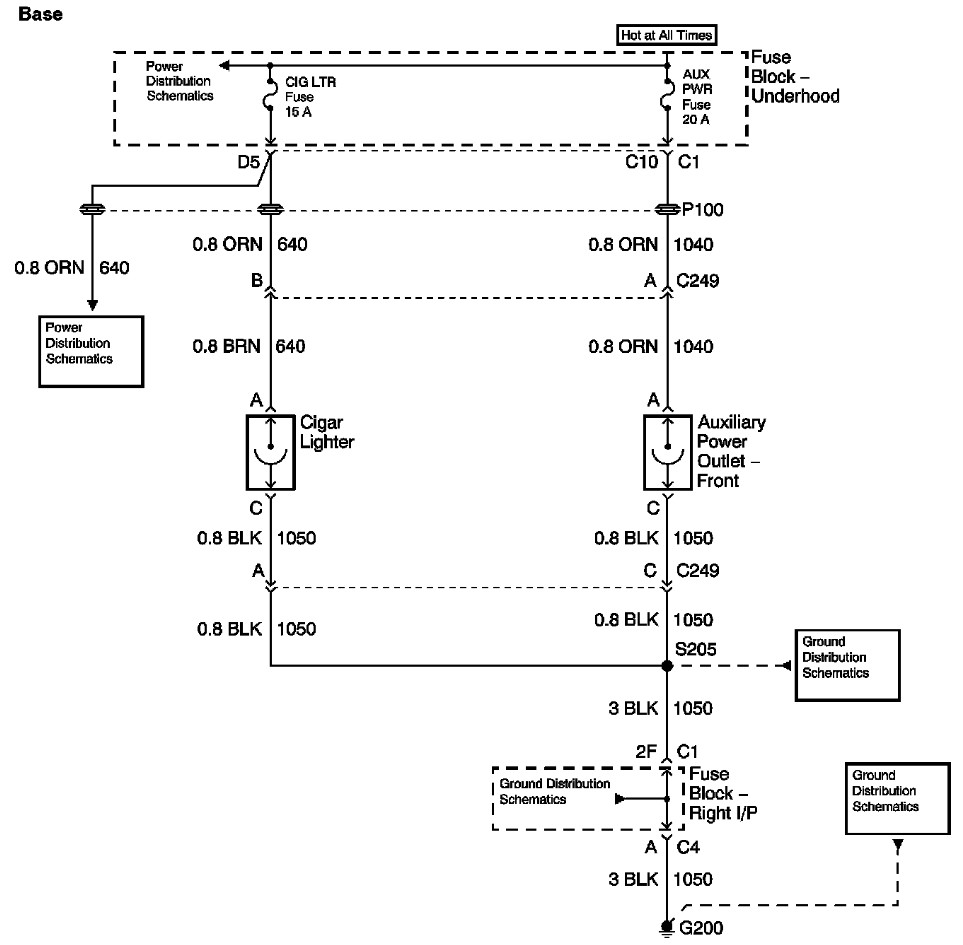
The provided information includes a fuse block diagram with the Auxiliary Power (Aux Pwr) fuse highlighted. It is advisable to check both sides of the fuse using a test light or multimeter to ensure functionality. It is assumed that...
The objective of this project is to create a controller-based model that counts the number of individuals entering a specific room and activates the lighting accordingly. This is achieved through the use of sensors that detect the current number...
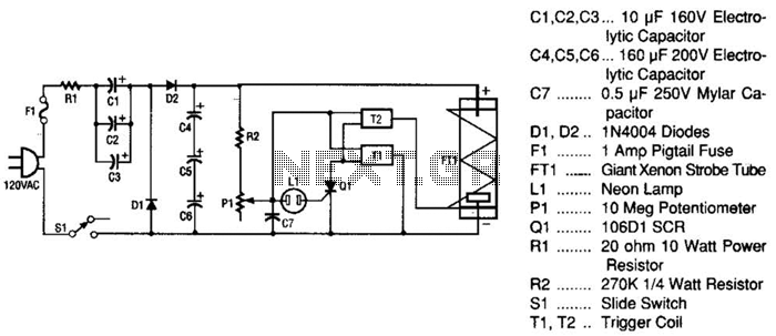
This strobe light operates from standard 120-Vac power. Resistor R1 limits the amount of current applied to the voltage doubler stage, which consists of capacitors C1, C2, C3, and diodes D1, D2, along with capacitors C4, C5, and C6....