
Strobe Light Circuit
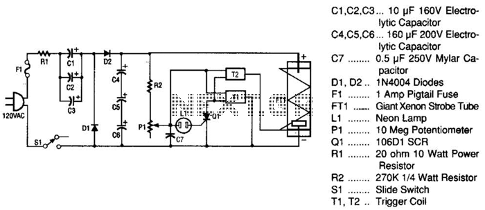
The next stage of the circuit is the neon relaxation oscillator and trigger stage, which includes resistor R2, potentiometer P1, capacitor C7, inductor L1, silicon-controlled rectifier (SCR) Q1, and transformers T1 and T2. As the storage capacitor (composed of C4, C5, and C6) reaches full capacity, the voltage divider formed by R2 and P1 applies voltage to capacitor C7. When C7 charges to a threshold voltage level, it triggers SCR Q1. Upon receiving a positive pulse at its gate, Q1 fires, creating a short circuit from anode to cathode. This action discharges most of the energy stored in C7 into the trigger transformers T1 and T2, which have secondary windings connected in series to generate 8 kV. The frequency of the 8-kV pulses is determined by the setting of potentiometer P1 and the value of capacitor C7. Since C7 is a fixed capacitor, only the adjustment of P1 influences the flash rate of the circuit. When an 8-kV pulse is applied from the secondary of T2 (trigger wire) to the trigger lead of the strobe tube, it discharges the storage capacitors C4, C5, and C6, causing the xenon strobe tube to ionize and flash. This cycle continues until power is removed from the circuit board by turning off switch S1 or disconnecting the line cord.
The strobe light circuit is designed to efficiently convert standard AC voltage into a high-voltage pulse suitable for triggering a xenon strobe tube. The voltage doubler stage ensures that sufficient voltage is available for the strobe operation, while the relaxation oscillator provides precise control over the flash rate. The use of diodes for rectification and SCR for triggering enhances the reliability and performance of the circuit. The combination of capacitors in both parallel and series configurations allows for optimized energy storage and discharge, crucial for the rapid operation of the strobe light. The overall design emphasizes simplicity and effectiveness, making it suitable for various lighting applications. This strobe light operates from standard 120-Vac power. Rl limits the amount of current applied to the voltage doubler stage, which is comprised of CI, C2, C3, Dl, D2, C4, C5, and C6. Capacitors CI, C2, and C3 are connected in parallel and form a capacitance of 30 at 160 V. Capacitors C4, C5, and C6 are connected in series and form an equivalent capacitor of about 53 at 480 V.
Diodes Dl and D2 not only rectify the ac voltage, but also complete the voltage doubler stage, which converts the incoming 120 Vac to the appropriately 300 V that are required by the xenon strobe tube. The next stage of the circuit is the neon relaxation oscillator and trigger stage. This stage is made up of R2, PI, C7, LI, Ql, Tl, and T2. As the storage capacitor (made up of C4, C5, and C6) reaches its full-capacity charge, the voltage divider (made up of R2 and PI) applies voltage to capacitor C7. As C7 charges up, it reaches a threshold voltage level, SCR Ql. When Ql has a positive pulse on its gate, it fires (causes a short from anode to cathode). That firing action discharges most of the energy stored in C7 into trigger transformers Tl and T2 (which have secondaries connected in scries to developer 8 kV).
The frequency of the 8-kV pulses is determined by the setting of PI and the value of CT Because C7 is a fixed capacitor, only the setting of PI adjusts the flash rate in this circuit. As soon as an 8-kV pulse is applied from the secondary of T2 (trigger wire) to the trigger lead of FT1, it discharges storage capacitors C4, C5, and C6, which causes it to ionize (flash).
The cycle then repeats itself until the power is removed from the circuit board by turning off SI or removing the line cord. 🔗 External reference
Related Circuits
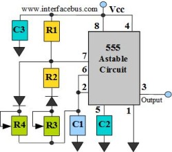
The astable multivibrator circuit lacks a stable state. In the absence of an external signal, the internal transistors alternately switch between cutoff and saturation at a frequency determined by the RC time constants of the coupling circuits. Therefore, an...
A diode, such as the IN4148, has a typical temperature coefficient of -2 mV/°C at a 1 mA diode current. Transistors Q1 and Q2 form a constant current source. Diode D1 serves as the temperature sensor. Integrated circuits ICl-a...
Power an RS232-TTL converter circuit using the serial port to eliminate the need for an external power supply. It has been noted that the DTR, RTS, and TD pins can facilitate this. Since the TD pin is already utilized...
LBl690 is a three-phase brushless DC motor drive control integrated circuit manufactured by Sanyo, a Japanese company. It is extensively utilized in both domestic and imported applications for broken wind and fresh air conditioning systems that require brushless DC drive...
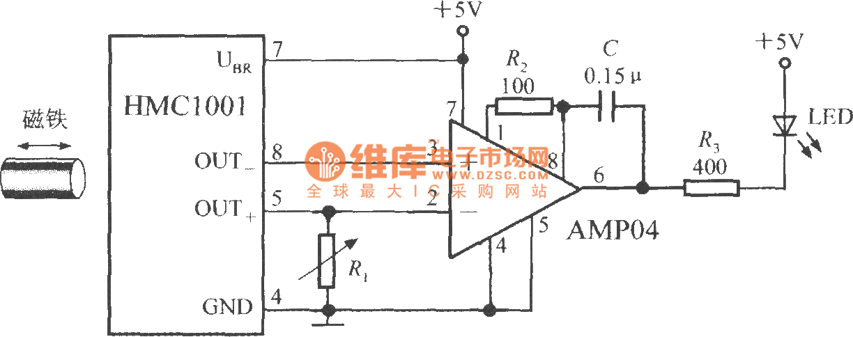
The proximity switch circuit consists of the HMC1001 sensor, operational amplifier (AMP04), and a light-emitting diode (LED). The operational amplifier functions as a comparator. When a magnet, measuring between 6mm and 12mm, is moved to a predetermined position near...
A request for a DIY 300BSE power amplifier schematic is made, with a specification to utilize Lowther PM6 speakers. The 300BSE power amplifier is a well-regarded audio amplification circuit known for its warm sound and high fidelity, particularly suited for...
Warning: include(partials/cookie-banner.php): Failed to open stream: Permission denied in /var/www/html/nextgr/view-circuit.php on line 713
Warning: include(): Failed opening 'partials/cookie-banner.php' for inclusion (include_path='.:/usr/share/php') in /var/www/html/nextgr/view-circuit.php on line 713