
Solid State Free energy Circuit
This circuit design utilizes capacitors as energy storage elements to create a self-sustaining system capable of powering a load, while also demonstrating principles of energy recovery and conversion. The core components include three capacitors (C1, C2, and C3), a motor, a generator, and a switching mechanism.
Initially, capacitor C1 is charged to 12 volts. A switch (S1) is employed to discharge C1 through the motor, which simultaneously powers the load and transfers energy to capacitor C2 until both capacitors reach 6 volts. Once C1 and C2 are sufficiently charged, switch S1 is opened, and switch S2 is closed. This action directs the energy stored in C2 into a DC-DC converter, which recharges C1 back to its original 12-volt state.
To enhance the system's efficiency and ensure continuous operation, a mechanical generator is integrated into the design. A permanent magnet motor is connected to a mass that provides additional inertia, facilitating smoother transitions during the switching process. After the initial charge from an external battery, the system operates autonomously by cycling the charge between the capacitors and the motor.
The operational sequence begins with the external battery charging the motor. Once the motor reaches operational speed, the battery is disconnected. C1 discharges into C2 through the motor, allowing both capacitors to share energy. The switching circuit then alternates the connections, allowing C3 to be charged by the generator while simultaneously discharging into the load.
This design aims to create a closed-loop system where the energy output exceeds the energy input, a condition referred to as operating "over unity." The effective management of energy transfer among the capacitors and the motor is crucial for maintaining the system's efficiency and achieving the desired performance. The proposed circuit requires careful consideration of component ratings, switching timing, and energy losses to ensure optimal functionality.It's very simple actually. The idea is that we use what we have learned from the capacitor tests to create a circuit that uses the capacitors to run the load and then by discharging the 1/2 full capacitor into a DC-DC converter we can recharge the initial cap and start again. And have some energy left over! So how can we use this to build a free energy generator? I believe there are 2 ways of doing it: - By building a Solid State free-energy circuit - By building a Mechanical generator free-energy machine Its very simple actually. First we charge C1 with 12 volts. Then we close S1 and discharge C1 through the motor and into C2. Now C1 and C2 are both at 6v and we got the motor to run for a while. Now make sure S1 is open and close S2. This discharges C2 into the DC-DC converter, which now charges C1 back to 12v. Open S2 and we can repeat it again and again.... And we now have Free energy! Then we just need to build a circuit to replace the manual switches. # Free-energy generator (mechanical) Well we have already proven that we have free energy available from doing the capacitor tests, now we need to come up with a way to convert that extra energy to be used in a closed loop system ie..
to charge a battery maybe. The problem with close looping it with a battery is that it is difficult to tell if the machine is running over 100% efficiency. Therefore I propose we use large capacitor banks. This way we can start the device with a battery and once it is up to speed, we disconnect the battery and let the capacitors do the rest.
We will know if it's running over unity right away if it doesnt stop within a minute or so. # Heres how it will work First off we add another capacitor C3. We build a device as shown with a high efficiency permanent magnet motor driving a generator. We attach a 5 pound mass to the drive shaft of the motor to give us some extra inertia during switching. The whole system will require a bit of switching to enable it to work properly. First we connect the external battery to the motor and let it spin up to speed. Next we disconnect the battery and C1 now discharges through the motor into C2. C1 and C2 now each have a 6-volt charge. Then our switching circuit discharges C1 directly across the motor with its 6-volt charge. Now C2 is discharged across the motor with its 6-volt charge. Meanwhile the generator has been hooked to C3, which is now charged, and ready. C3 now switches connections with C1 i.e.. C1 is now being recharged by the generator and C3 is dumped through the motor into C2. The cycle then continues. The system will operate over unity just as our simple capacitor tests proved. 🔗 External reference
Related Circuits
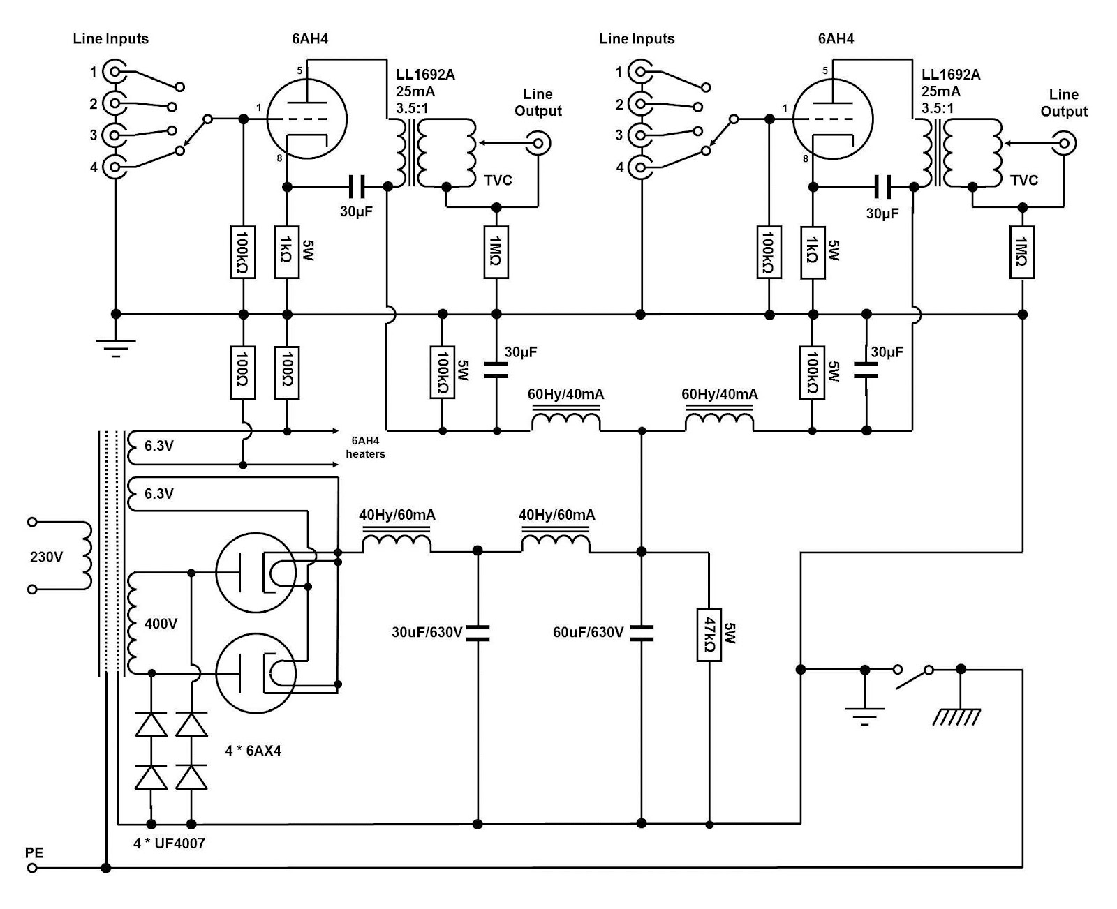
The circuit and assembly process of the line stage is presented in two separate articles. This linestage shares the same circuit as the two chassis version previously described. However, in this design, the power supply and preamplifier are housed...
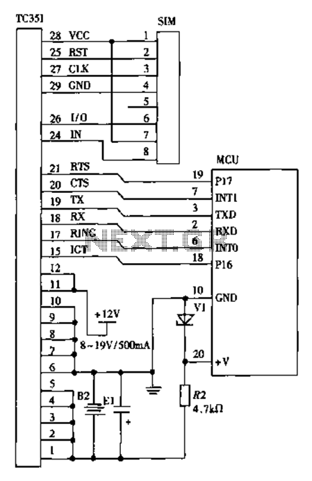
The design of a wireless data communication circuit is primarily intended for motor vehicles and fixed base station systems to facilitate close-range wireless data exchange. The circuit is based on the core chip nRF401 and its associated components. The...
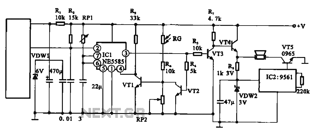
This circuit illustrates an automatic unattended burglar alarm system designed primarily for residential use, warehouses, and similar applications. The circuit features a pyroelectric infrared sensor integrated with a light control mechanism. It comprises components such as resistors (RG, RP2,...
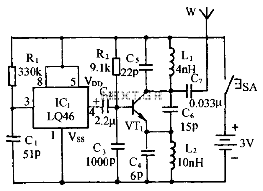
The circuit is presented, consisting of a language and sound circuit FM transmitter. It is simple and easy to manufacture, compatible with ordinary FM radios, allowing for potential listening scenarios and preventive measures. The FM transmitter circuit is designed to...
The output frequency can be altered based on the division ratio of the comparison frequency in the 10 kHz unit, with the division ratio set to 1024 in this circuit. Given that the amateur radio bandwidth in Japan is...
The FM302E-I-type FM transmitter exciter is utilized in Japan's NEC HPB a 1210 motherboard. It features direct carrier frequency modulation, phase-locked frequency stabilization, and frequency synthesis. The preamplifier (BLF-177 FET) is directly driven by an actuator, achieving a maximum...