
bluetooth curtain system
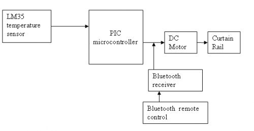
The circuit design for the DC motor and Bluetooth system comprises several critical components and connections to ensure proper functionality. At the core of the system is a PIC microcontroller, such as the PIC16F877, which serves as the primary control unit. The microcontroller interfaces with a Bluetooth receiver module, which facilitates wireless communication with a mobile device running a J2ME application. The Bluetooth receiver's output is connected to specific input pins on the microcontroller, allowing it to interpret commands sent from the mobile device.
The DC motor, responsible for opening and closing the curtain, is connected to the microcontroller via a motor driver circuit, such as the L293D. This motor driver is essential for controlling the direction and speed of the motor. The L293D allows for the implementation of an H-bridge configuration, enabling the motor to rotate in both forward and reverse directions. Pulse Width Modulation (PWM) can be employed to adjust the motor's speed, providing finer control over the curtain's movement.
To ensure accurate feedback on the curtain's position, an LM35 temperature sensor can be integrated into the system. This sensor connects to one of the microcontroller's analog input pins, allowing the PIC to monitor environmental conditions, which may influence the motor's operation.
The J2ME application, developed for mobile devices, will feature a user-friendly graphical interface that allows users to send commands to the Bluetooth receiver. The application should be programmed to send specific characters or commands that correspond to the desired motor actions, such as opening or closing the curtains. Upon receiving these commands, the Bluetooth receiver transmits the data to the PIC microcontroller, which processes the information and activates the motor driver accordingly.
For successful implementation, it is crucial to refer to the datasheet of the PIC microcontroller to identify the appropriate pins for connecting the Bluetooth receiver, motor driver, and LM35 sensor. This will ensure that all components are correctly integrated into the circuit, facilitating seamless communication and control over the curtain operation. The selection of a suitable DC motor should also be based on the load it is expected to handle, prioritizing torque over speed to effectively manage the curtain's weight.Designing the circuit for the DC motor and bluetooth system. The bluetooth remote control is used to open and close the curtain. Below is the block diagram for your reference. 2. You can make use of your mobile phone, write a J2ME application for communicating with your hardware. that will also give you extra control and a nice GUI interface. GUI is just a graphical user interface. its not related to windows, but its a term used for interface that is graphical to user. can be on any platform or even without platform. You mean i can create a J2ME application using the tool in the link page Is it to use the same coding in the website to develop a software to communicate between mobile phone and the controller. How to program the J2ME application to enable the dc motor to move reverse and forward as it is also connected to a PIC microcontroller Do i need additional circuit dc motor speed can also be done by using h-bridge with pwm but if u want to use simple on off it then also h-bridge can be used or use simple relay control method program the J2ME application in such a way u send any character in J2ME coding blue tooth receiver receive that character and sent to pic then pic should know that what have to done it this character received which pin do i connect the bluetooth receiver if i use PIC16F877 how do i read the datasheet to know which pin to connect which component how to know which pin to connect the input from LM35 sensor and the output for motor having trouble to understand the datasheet.
LM35 will go to analog input pin you can select any. motor will be connected through a motor driver e. g. L293D (see dc motor tutorial for info on connections). finish motor rotation part first then go to bluetooth. ajay want to say that u first complete motor driving portion mean if ur using h-bridge or whatever method try to run first so its sure that this portion is working properly may i know why the bluetooth receiver must be connected to the PIC microcontroller Can`t it be directly connected to the motor driver How do i know this PIC microcontroller is suitable for the bluetooth receiver Which part in the datasheet should i refer to when u attach it to controller u send a character when this character is recieved at reciever end and reach to controller now controller know the meaning of this character that moving motor right of left etc is it all the bluetooth device have serial interface can you suggest type of DC motor which is suitable and got enough powerto be used to open and close the curtain selection of motor depends on type of load you are going to put on them. you dont need a high RPM motor, but you need motor with enough torque to pull your curtains. does the motor circuit require a motor drive to rotate the motor What software need to be used to design J2ME application It seems the Java wireless Toolkit CLDC cannot be used to coding the software.
What is the use of Java Wireless Toolkit CLDC The Sun Java Wireless Toolkit (formerly known as Java 2 Platform, Micro Edition (J2ME) Wireless Toolkit) is a state-of-the-art toolbox for developing wireless applications that are based on J2ME`s Connected Limited Device Configuration (CLDC) and Mobile Information Device Profile (MIDP), and designed to run on cell phones, mainstream personal digital assistants, and other small mobile devices. 🔗 External reference
Related Circuits
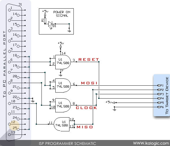
In-System Programming (ISP) allows for the serial programming of a microcontroller while it remains on the board, eliminating the need to remove the chip. This method provides a straightforward and cost-effective solution for programming and debugging microcontroller-based projects, whether...
The power-supply sequencing tutorial utilizes the MAX16046 system-management integrated circuit (IC). The configuration software facilitates the setup of tolerances and the sequence order. The MAX16046 is a versatile system-management IC designed to manage power-supply sequencing in complex electronic systems. It...
The circuit is activated by an LED/photoresistor isolator (U1), which combines a light-dependent resistor (LDR) and an LED in a single package. This device was selected for its high isolation characteristic of 2000 V, which is essential since the...
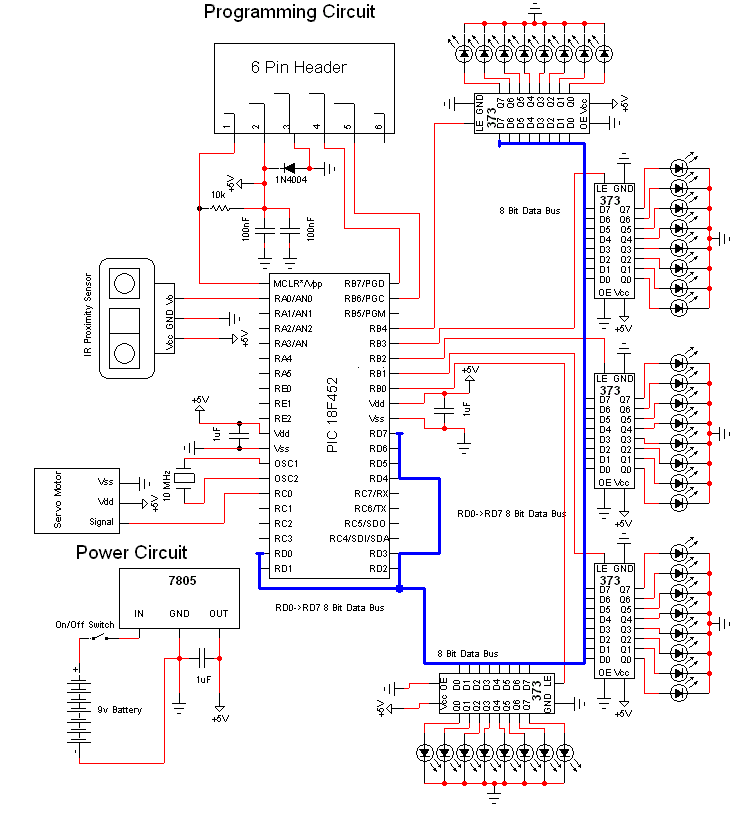
This document discusses a do-it-yourself alarm system utilizing the PIC18F452 microcontroller. It is a highly engaging project, although the schematic is quite complex. The project employs three main components to create the personal alarm system. The infrared (IR) proximity...
The PIC16F870 keeps track of battery voltage as well as both charging and discharging currents. It also drives the 4 digit display and switches the AC and load relays. The basic operation is as follows: While AC power is...
The ISL62381, ISL62382, ISL62383, ISL62381C, ISL62382C, and ISL62383C family of controllers generate supply voltages for battery-powered systems. These controllers include two pulse-width modulation (PWM) controllers, adjustable from 0.6V to 5.5V, and two linear regulators, LDO5 and LDO3, that generate...