
Strobe Alert System Circuit

When the internal LED lights, the LDR's resistance decreases to around 5 kΩ. Under this condition, approximately 125 Vdc is applied across C1, R4, and C2. The neon lamp periodically fires and extinguishes as capacitor C3 charges through R4 and discharges via NE1 and the SCR gate. Resistor R4 limits the current input to C3, thereby controlling the firing rate of NE1 to about three times per second. The discharge through NE1 is applied to the gate of SCR1. SCR1, a sensitive-gate unit, activates immediately when NE1 conducts, completing the ground circuit for transformer T1 (a 4-kV trigger transformer). As SCR1 toggles on and off in synchronization with the firing of NE1, capacitor C2 (connected in parallel with T1's primary) charges via R1 and then discharges rapidly through T1's primary winding. A voltage pulse is applied to the trigger input of FL1, a Xenon flash lamp. It is important to note that the circuit is connected directly to the AC line. Resistor R6 is included to limit the amount of line current available to the circuit. The value of R6 can be decreased if modifications are intended for increased flash power. Caution is advised; even though the circuit is fuse-protected, it can still be hazardous if mishandled.
The circuit design utilizes an LED/photoresistor isolator (U1) to provide electrical isolation while allowing light detection, crucial for applications where safety is paramount due to the direct connection to the AC line. The high isolation voltage of 2000 V ensures that any high-voltage spikes do not affect the low-voltage components of the circuit. The voltage divider formed by R2, U1's internal resistance, and R3 is essential for controlling the voltage levels seen by the subsequent components, particularly NE1, which requires careful voltage management to prevent premature activation.
The operation of the circuit hinges on the behavior of the LDR within U1. When the internal LED is off, the high resistance of the LDR prevents significant voltage from reaching NE1, thus maintaining a safe operating condition. However, when the internal LED is activated, the resistance drops, allowing a sufficient voltage to build up across the components, leading to the firing of the neon lamp. This firing is critical for producing the necessary voltage pulse that triggers the Xenon flash lamp (FL1).
The design also incorporates a feedback mechanism through the use of capacitor C3, which charges and discharges, controlling the firing rate of NE1. This feedback loop is crucial for maintaining consistent operation and preventing overheating or damage to the components. The use of SCR1 as a switching element allows for rapid on-off control, essential for the operation of the trigger transformer (T1) and ensuring that the Xenon flash lamp fires at the desired frequency.
Overall, the circuit's design is a sophisticated integration of light sensing, voltage isolation, and high-voltage switching, making it suitable for applications in photography, strobe lighting, and other areas requiring precise control of high-voltage flash outputs. Proper handling and safety precautions are necessary due to the inherent risks associated with high-voltage circuits. The circuit is activated by an LED/photoresistor isolator (Ul), which is a combination of a light-dependent resistor (LDR) and an LED in a single package. That device was chosen because of its high isolation (2000 V) characteristic, which is necessary because the strobe part of the circuit is directly connected to the ac line.The voltage divider is formed by R2, Ul`s internal resistance, and R3.
When Ul`s internal LED is off, Ul`s internal LDR has a very high resistanceon the order of 10 . The voltage applied to NE1 is considerably below its ignition voltage of approximately 90 Vdc.The optoisolator`s internal LED is activated by a dc signal supplying 20 mA. The external sensor (s) that supply the signal are connected to the strobe part of the circuit at,11 and J2.
When the internal LED lights, the LDR`s resistance decreases to around 5 kQ. Under that condition, about 125 Vdc is applied across CI, R4, and C2. The neon lamp periodically fires arid extinguishes as capacitor C3 charges through R4, and discharges via NE1 and the SCR gate.Resistor R4 restricts the current input to C3, and thereby controls the firing rate of NE1about three times per second. The discharge through NE1 is applied to the gate of SCR1.SCR1, a sensitive-gate unit, snaps on immediately when NE1 conducts, which completes ..the ground circuit for transformer T1 (a 4-kV trigger transformer).
As SCR1 toggles on and off in time with the firing of NE1, capacitor C2 (connected in parallel with Tl`s primary) charges via Rl, and then discharges very rapidly through Tl`s primary winding. A voltage pulse is applied to the trigger input of FL1, a Xenon flash lamp.It is important to remember that the circuit is connected directly to the ac line.
Resistor R6 is included to limit the amount of line current available to the circuit. The value of R6 can be decreased if you intend to modify the circuit for more flash power.Warning: Even though the circuit is fuse-protected, it can still be dangerous if handled carelessly. 🔗 External reference
Related Circuits
The circuit consists of a light metering circuit and a flash circuit, as illustrated in the accompanying image. It is designed for use with integrated cameras such as POPTICS, Franka X-500, and WIZEN-860S. The circuit includes the following components:...
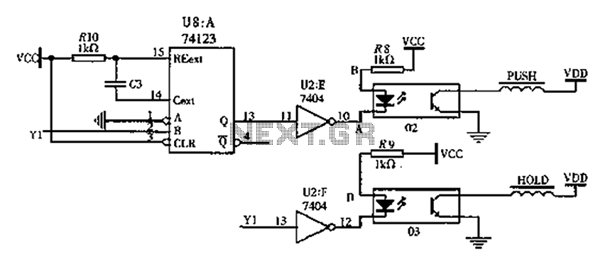
The FIG switching solenoid driver circuit utilizes the 74123 device chip (U8) and solid-state relays (02, 03). The switching electromagnet coil is referred to as the PUSH coil, while the HOL is maintained at a power supply voltage (VDD)...

The LM386 is an ideal choice for a door phone application. This device is particularly beneficial in modern urban households, utilizing a condenser microphone and a speaker. The LM386 is a low-voltage audio power amplifier that is commonly used in...

The Switchgate is a simple dual gate circuit based on a 556 timer configured in monostable mode, featuring a trigger input that activates two switches. The outputs of the monostables are also available individually. Recent research has led to...
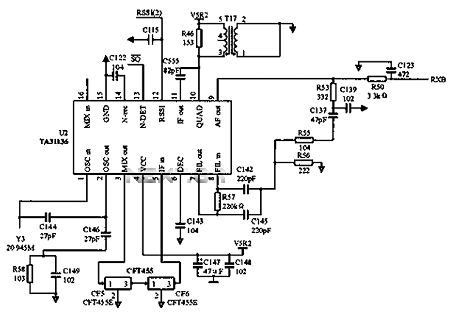
As illustrated in the figure, Vcc is the power supply for the circuit. Upon receiving the initial signal, the frequency is adjusted to 21.7 MHz. This frequency is subsequently enhanced through two crystal filters to improve the selectivity of...

At the core of this circuit is the KTY10 temperature sensor from Siemens. This silicon sensor functions as a temperature-dependent resistor, integrated as one arm of a bridge circuit. A preset potentiometer (P1) is used to balance the bridge...