
Backup Power System with PIC16F870
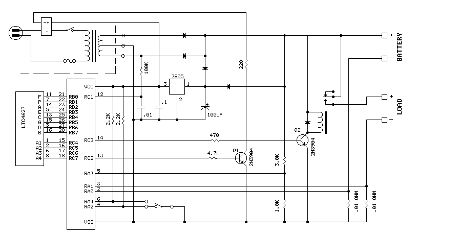
In order to measure currents up to 10 amps, 0.01 ohm resistors were made out of about 5 inches of #22 solid hookup wire. A simple resistor divider is used to monitor the voltage.
Since this is a Pulsed charging system (note lack of humongous filter capacitors), the battery voltage is only measured between the charge pulses. The AC connection to RC1 is used to synchronize this operation. Also, making a reasonable current measurement is done by summing several samples spaced over one complete charge pulse interval. In other words, the actual charge is going on only about 20 percent of the time. So taking samples over the entire interval automatically 'does the math'.
The circuit employs a PIC16F870 microcontroller, which serves as the central processing unit for monitoring battery conditions and controlling the associated relay systems. The microcontroller interfaces with a 4-digit display to present real-time battery voltage and current readings, ensuring user visibility of the system's operational status. The design incorporates a load relay that connects to a 12V DC system, which powers various devices such as lights and fans when the AC power source is unavailable.
To prevent battery damage, the system continuously monitors the battery voltage. If the voltage drops below a predetermined threshold, the load relay is disengaged to protect the batteries from over-discharging. The monitoring of charging and discharging currents is achieved through precision resistors (0.01 ohms) made from #22 solid hookup wire, which allows for accurate current sensing up to 10 amps. The voltage across these resistors is measured using a resistor divider network, providing proportional voltage levels suitable for the microcontroller's analog input.
The charging system operates in a pulsed mode, which is characterized by the absence of large filter capacitors typically found in linear power supplies. Instead, the battery voltage is sampled only during charge pulses, with synchronization provided by the AC connection to RC1. This sampling strategy allows for efficient measurement of battery conditions, as the actual charging occurs for approximately 20% of the time, enabling the system to calculate average current over the entire pulse interval.
The redesign of the power management system involved the removal of an SCR previously used for switching power from the rectifiers to the battery. This was replaced with a solid-state relay positioned in the primary circuit of the transformer, which significantly reduces idle current draw. The configuration enhances overall efficiency while maintaining reliable operation of the battery management system.The PIC16F870 keeps track of battery voltage as well as both charging and discharging currents. It also drives the 4 digit display, and switches the AC and load relays. The basic operation is as follows: While AC power is available, the battery voltage is constantly monitored and topped off as needed. When the AC power fails, the load relay engages the 12-volt system. This connects to lights, fans, and other 12 volt devices as needed. Should the battery voltage fall too low, the load relay is disengaged, preventing the acid batteries from being damaged by over discharging.
Refering to the SCHEMATIC, which differs some from the LAYOUT, the planned SCR that switched power from the power rectifiers to the battery was eliminated from the design. (This left a redunant diode feeding power to the 7805). Instead, a 110 volt solid-state relay was added to the transformer primary circuit. This eliminated the rather large idling current from the scrounged transformer. In order to measure currents up to 10 amps, .01 ohm resistors were made out of about 5 inches of #22 solid hookup wire.
A simple resistor devider is used to monitor the voltage. Since this is a Pulsed charging system (note lack of humongus filter capacitors), the battery voltage is only measured between the charge pulses. The ac connection to RC1 is used to synchronize this operation. Also, makeing a reasonable current measurement is done by summing several samples spaced over one complete charge pulse interval.
In other words, the actual charge is going on only about 20 percent of the time. So taking samples over the entire interval automatically 'does the math'. 🔗 External reference
Related Circuits
This circuit was requested by several correspondents. Its purpose was to obtain more power than the siren circuit already available on this website (One-IC two-tones Siren) and to avoid the use of ICs. A complementary transistor pair (Q2 &...
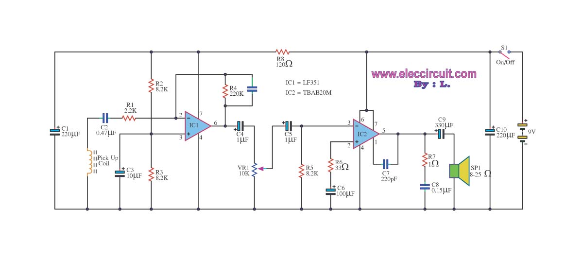
The circuit is designed to amplify telephone signals using a 2W+2W amplifier with an 8-ohm loudspeaker. It provides adequate sound output while maintaining good audio quality. The primary component of this telephone amplifier circuit is the IC LF351, which...

A radio camera on a model railway should transmit constantly while the train is moving and continue transmitting for a few minutes after the train stops. The design of a radio camera system for a model railway requires careful consideration...
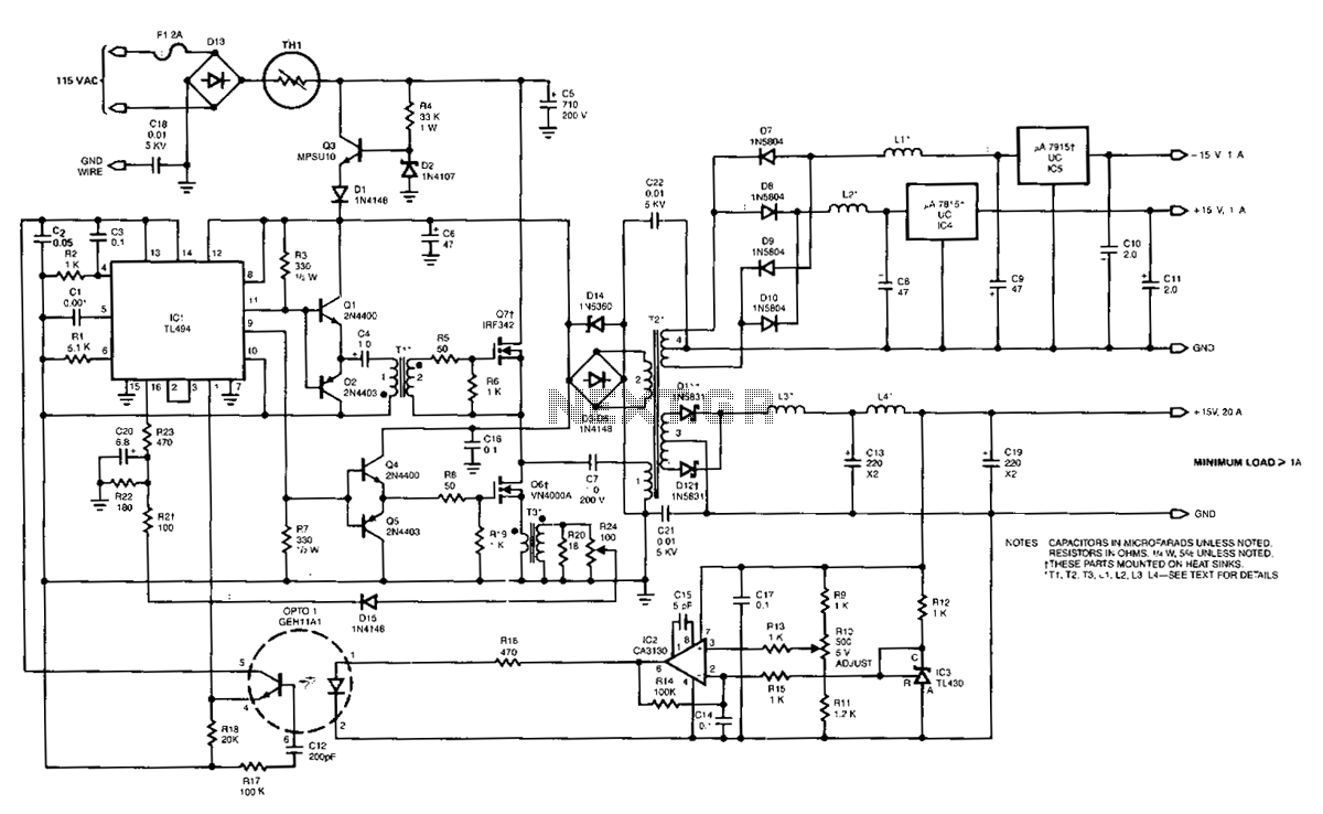
The power supply employs two VN4000A 400-V MOSPOWER FETs configured in a half-bridge arrangement. It provides outputs of +5 V at 20 A and ±15 V (or ±12 V) at 1 A. The low-current outputs utilize linear three-terminal regulators,...
A power amp designed for use in low voltage, especially battery-operated, applications. For minimum parts count, C1 and C2 can be omitted. More: With pins 1 and 8 open circuit the gain in internally set to 20 dB. The described...
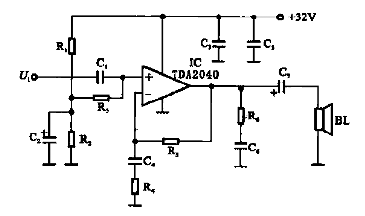
An integrated power amplifier TDA2040 is used in an OTL (Output Transformer-Less) power amplifier circuit, which operates with a +3V single supply as the working voltage. This circuit has a voltage gain of 30 dB (approximately 32 times magnification),...