
Boba Fett project movement
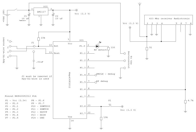
The described timer circuit is integral for controlling a servomotor's movement with precision. The timer's ability to generate a consistent 20 ms period allows for fine control over the output signal frequency, which is essential for servomotor applications. The division of this period into 256 steps through an 8-bit variable provides a high resolution for position control, enabling the servomotor to respond accurately to user inputs.
The duty cycle variable plays a crucial role in determining the servomotor's position. By preloading the start and end positions, the system can ensure that the motor reaches its target position at maximum speed, enhancing responsiveness. The S2 pushbutton serves as a trigger, initiating the movement sequence, which is critical for applications requiring immediate action.
The choice of a 50 Hz frequency is significant; it strikes a balance between speed and feedback, allowing the servomotor to execute movements smoothly while maintaining stability in its position. The system's design to interpret frequency rather than simple on/off signals adds robustness, as it can differentiate between valid commands and noise. This capability is vital in noisy environments where interference could otherwise lead to erratic behavior.
The implementation of timer interrupts to monitor the input line further enhances the reliability of the system. By expecting a defined number of high and low readings, the circuit can effectively filter out noise, ensuring that only valid signals are acted upon. This approach mitigates the risk of false triggering due to transient disturbances.
Overall, this timer-based control mechanism for servomotors exemplifies a sophisticated approach to electronic design, leveraging precise timing and signal processing to achieve reliable and responsive control in various applications.the timer will generate the basic period (for example 20ms) and with some associated variables will be possible to "fire" an I/O pin to generate the signal. For example, using a 8 bit variable, we can divide the generated frequency in "chunks" of 256 (8 bit = 256), so basically we can have 256 "steps" each one of 0.
078125 ms (20 ms / 256 = 0. 078125). The start and end positions are loaded immediately in the duty cycle variable, so the servomotor can reach the positions at full speed every time the S2 pushbutton is pressed. The frequency of the command pulse determine how fast the servo "execute" the movement and the "strenght" to retain the position.
The default frequency used is 50 Hz because has the right speed and feedback speed. The module is designed to receive a frequency, not a simple on/off signal, so we have to assume a precise frequency as indication of triggering the arm, or ON condition, and the absence of this frequency as OFF condition. After that, knowing the front of the wave was detected, every timer interrupt (the wave below represent the timer) we read the input line and we expect a determined amount of readings high and a determined amount of readings low.
In absence of signals, the receiver picks up anyway some "noise", and this noise can sometime have the same frequency of the valid signal, but for short time. 🔗 External reference
Related Circuits

In practical applications, a series resistance must always be included. This component serves the dual purpose of limiting the current at pin 7 and smoothing the ON/OFF transitions during standby. In electronic circuits, particularly those involving integrated circuits (ICs) or...

An audio filter is positioned at the input of each audio integrated circuit (IC) chip to filter the audio signal intended for speakers. A low-pass filter is utilized for the woofer, while a high-pass filter is employed for midrange...
The switch control system utilizes sensors to inform the microcontroller of the trains' positions on the layout. This ensures that only one train occupies the main line at any given time and that switches are correctly set for the...

On a mountain bike, a common issue with traditional flashing LED lights from stores is the frequent problem of flat batteries and lights detaching. As an electronics student, a better solution was sought. A front wheel with a built-in...
.jpg)
This project is a combined temperature and humidity meter. It is an enhancement of a previous PIC-based humidity meter and PIC and AVR thermometers. The design utilizes an ATmega164 microcontroller, which offers ample input/output ports and memory. The humidity...

A simple low-power AM/FM radio receiver electronic project can be designed using the TA8122 integrated AM/FM receiver, manufactured by Toshiba Semiconductor. This radio receiver circuit is suitable for portable radio applications and similar devices. The TA8122 radio receiver circuit...
Warning: include(partials/cookie-banner.php): Failed to open stream: Permission denied in /var/www/html/nextgr/view-circuit.php on line 713
Warning: include(): Failed opening 'partials/cookie-banner.php' for inclusion (include_path='.:/usr/share/php') in /var/www/html/nextgr/view-circuit.php on line 713