
AVR Projects
.jpg)
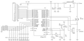
The combined temperature and humidity meter circuit integrates several key components and design considerations to achieve accurate measurements and reliable performance. The ATmega164 microcontroller serves as the central processing unit, managing data acquisition from the sensors and controlling the display output. The HS1101 humidity sensor operates on a principle that requires careful placement to minimize noise interference, which has been addressed by positioning it in close proximity to the LMC555 timer.
The LMC555 timer is configured in a stable mode to generate a square wave output, which is crucial for the humidity measurement process. The output frequency of the HS1101 is directly related to the humidity level, allowing the microcontroller to calculate humidity by measuring the frequency of the square wave signal. Timer0 is programmed to generate regular intervals, facilitating consistent readings and ensuring that the microcontroller can process data without delays.
The LCD display, although lacking a backlight, is driven directly by the microcontroller through a large number of connections. This design choice reflects a trade-off between cost and functionality, as the static LCD provides sufficient visibility for short usage periods. The absence of a backlight is mitigated by the display's ability to maintain contrast temporarily after power-up, making it suitable for brief readings.
Power management is another critical aspect of the design. The unit operates on batteries, with a power supply regulator ensuring stable voltage to the microcontroller and sensors. The inclusion of an external power supply option enhances versatility, allowing the device to be powered continuously when necessary.
In summary, this combined temperature and humidity meter project demonstrates an effective integration of microcontroller technology, sensor design, and power management strategies to deliver a functional and compact measuring instrument. The enhancements made over previous designs address earlier challenges and improve overall usability, making it a valuable tool for environmental monitoring applications.This project is a combined temperature and humiditymeter. It is an improvement on my PIC-based humidity meter and my PIC and AVR thermometers. I use an ATmega164, which as lots of I/O and memory. The humidity sensor is a HS1101, made by Parallax (p/n 27920) and available from Digikey (27920-ND) for around US$10. The circuit for the humidity meter sensor is identical to the earlier project. I had made a mistake in construction, which resulted in erratic operation. The problem is that the HS1101 must be physically as close to the LMC555 as possible. I had runa 4-inch wire to the circuit board, and the unit became sensitive to noise picked up from the surroundings. In this version, I placed the sensor board at the top of the case, where the HS1101 can plug right in to the circuit.
and the HS1101 humidity sensor. The board at the top contains the LMC555 circuit and the power supply regulator. A 6 conductor cable goes the the lower board, which contains the CPU. The middle board has the LCD display and 2 switches. The switches hold the board in place. There is a 26 conductor ribbon cable to the CPU board just below. Since the LCD uses little power, the unit is battery operated (with provision for an external power supply), another big improvement over the older projects. The battery and holder are at the bottom of the case. The power leads go to the on/off switch (SW1) and then to the sensor board regulator, and regulated power goes to the CPU board.
with no controller or backlight. I must admit that this LCD display is a pain to use. You need 24 connections to the CPU (hence the large ribbon cable in the photo), and the program must drive each segment to make up the display. However itis cheap (
A very good write-up on the subject can be found here. However I did not implement this, as I find that the Lumex display maintains its contrast for some time after power-up. I never leave the unit on for more than a few seconds at a time, so this is not a problem for me. When you switch the unit on, the battery voltage is sampled via R5 and R6 and ADC0. For 2 or 3 seconds, the battery voltage is displayed. Then the display changes to temperature or humidity, depending on the setting of SW2. Other improvements are the choice of Celsius or Fahrenheit (JP1), and the ability to display negative temperatures.
The temperature sensor is connected to ADC7 and uses the internal 1. 1V Vref. A digital median filter is used to smooth out the temperature display. The humidity circuit generates a squarewave which is connected to T1. Timer0 is programmed to give 1 second intervals, where the T1 count is read and reset. An interpolating routine is used to get humidity from the measured frequency. 🔗 External reference
Related Circuits

The schematic includes programmable AVRs. For other members of the AVR family or additional programmable ICs compatible with Ponyprog, there is a J1 connector (CON10) that facilitates hardware expansion of the programmer. Additional information about compatible ICs can be...
A battery charger can be understood as a device designed to replenish the charge in a battery. An effective charger circuit should provide the necessary resources for efficient and safe battery charging. The AVR-Based Battery Charger utilizes the ATMega...
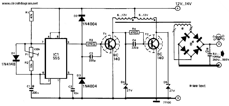
When the output of the multivibrator is low, Q1 (an NPN transistor) will be OFF and Q2 (a PNP transistor) will be ON. Consequently, the negative terminal of capacitor C3 will be connected to ground, allowing it to charge...
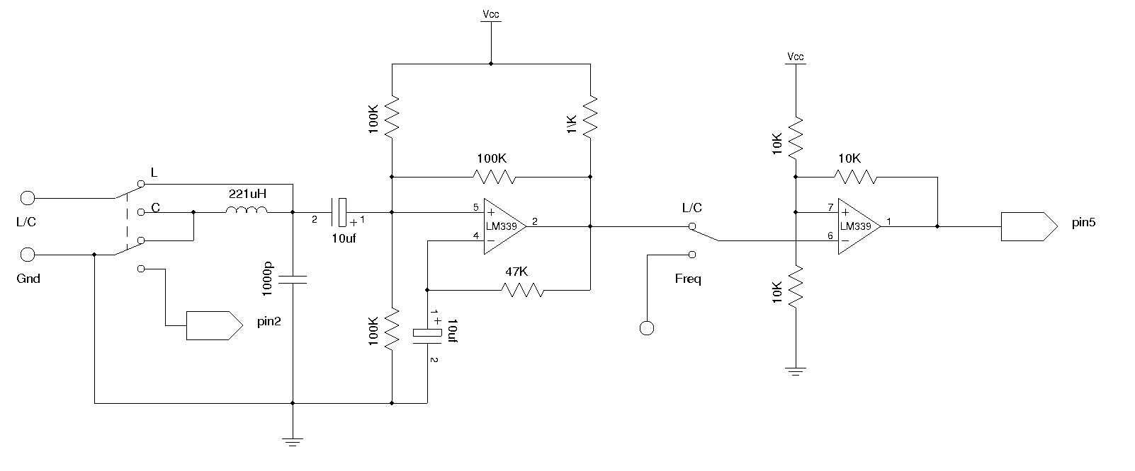
An LC meter is being constructed due to the absence of a multimeter capable of measuring inductance. Although the available multimeters can measure capacitance, they lack accuracy for small capacitance values in the range of several picofarads (pF). While...
The AVR 8-Bit RISC microcontroller from Atmel is a widely used microcontroller. This microcontroller integrates EEPROM, RAM, an Analog to Digital converter, numerous digital input and output lines, timers, UART for RS-232 communication, and various other features. An article...
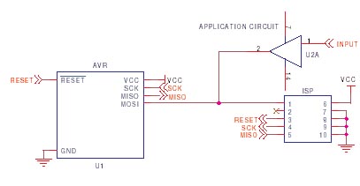
It is crucial to design the PCB layout correctly to enable seamless In-System Programming (ISP) of AVR microcontrollers. This guide addresses common issues encountered and provides typical AVR ISP circuit schematics. It focuses on Serial Programming, known as ISP,...