
Boombox circuit diagram

The circuit is designed to enhance signal integrity by utilizing a transistor as the primary amplification component. The transistor's role is to increase the amplitude of the incoming signal, making it suitable for further processing or output. The two diodes connected in the circuit serve as clamping devices, which effectively limit the voltage levels of the output signal. This clamping action prevents distortion that could occur due to excessive voltage swings, thereby preserving the quality of the amplified signal.
To address high-frequency noise, a 500 pF capacitor is integrated into the circuit. This capacitor acts as a low-pass filter, allowing lower frequency signals to pass through while attenuating higher frequency noise components. The selection of the 500 pF value is critical as it determines the cutoff frequency of the filter, ensuring that unwanted high-frequency signals are effectively removed from the output.
The inclusion of a 1M slide rheostat provides a means to adjust the noise intensity dynamically. This adjustable resistor allows the user to fine-tune the circuit's response to varying conditions, enabling a smooth transition from maximum noise to complete attenuation. This feature is particularly useful in applications where signal clarity is paramount, as it allows for real-time adjustments to accommodate different operating environments or signal conditions.
Overall, this circuit represents a robust solution for amplifying signals while mitigating distortion and noise, making it suitable for various electronic applications where signal integrity is essential. Circuit Description: Transistor can amplify the input signal. Then two diodes clamp distorted output, high-frequency noise is 500 pF capacitor filter out from the circuit. Unde r normal conditions, the slide rheostat 1M adjustable intensity noise, it changed from the maximum to zero.
Related Circuits

FAN7710 Ballast Control circuit design for Compact Fluorescent Lamps electronic project. The FAN7710 is a specialized integrated circuit designed for the control of ballast systems in compact fluorescent lamps (CFLs). This circuit typically operates in a high-frequency range, facilitating efficient...
This solid-state push-pull single-ended Class A circuit is capable of providing sound quality comparable to valve amplifiers, delivering an output power of 6.9W measured across an 8 Ohm loudspeaker cabinet load. It exhibits lower total harmonic distortion (THD), higher...
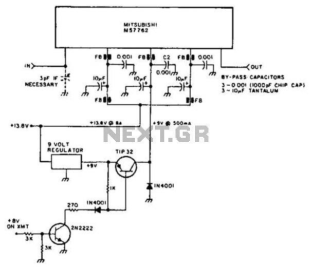
Using a Mitsubishi M57762 amplifier module, this amplifier delivers 20 W output at 1296 MHz. A single 12 V nominal power supply can be used. The Mitsubishi M57762 is a high-performance RF amplifier designed for applications requiring significant power output...
This lie detector circuit diagram provides two readings: one for challenging questions directed at the subject and another to display the subject's emotional state in general. The emotional states are detected not only by heart rate variations and perspiration...
This 5-volt Switch Mode Power Supply circuit utilizes an integrated circuit (IC) from National Semiconductor, which specializes in the production and design of ICs for switch-mode power supply applications. The 5-volt Switch Mode Power Supply (SMPS) circuit is designed to...
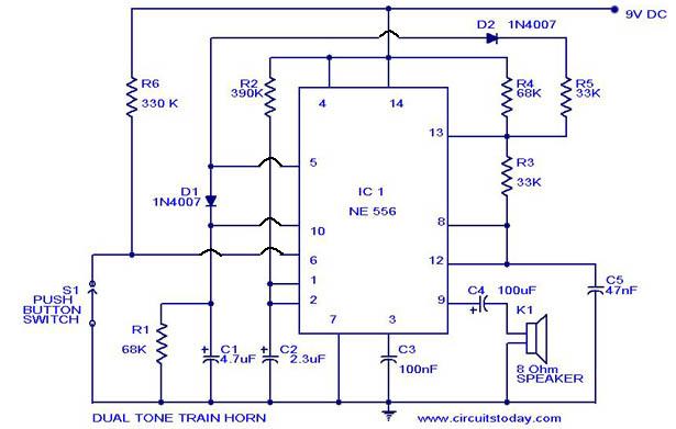
A dual-tone model train horn/sound generator/simulator circuit can be created using two NE 555 timers connected in cascade. However, the circuit diagram presented is designed with the NE 556 integrated circuit, which essentially comprises two 555 timers in a...