
FAN7710 Ballast Control circuit design

The FAN7710 is a specialized integrated circuit designed for the control of ballast systems in compact fluorescent lamps (CFLs). This circuit typically operates in a high-frequency range, facilitating efficient energy conversion and regulation necessary for the optimal functioning of CFLs. The FAN7710 incorporates various features aimed at enhancing the performance and reliability of the ballast control system.
The circuit design generally includes essential components such as inductors, capacitors, and resistors, which work in conjunction with the FAN7710 to create a stable operating environment for the lamp. The integration of feedback mechanisms is crucial for maintaining the desired output voltage and current, ensuring that the CFL operates within its specified parameters.
Furthermore, the FAN7710 supports features such as soft-start capabilities, which help to reduce inrush current during lamp ignition, thereby prolonging the lifespan of the CFL. The circuit may also incorporate protection mechanisms against over-voltage, over-current, and thermal overload conditions, enhancing overall safety and efficiency.
In terms of layout, careful attention must be paid to the placement of components to minimize electromagnetic interference (EMI) and optimize thermal management. Proper grounding and decoupling strategies are essential to ensure the stability of the circuit during operation.
Overall, the FAN7710 ballast control circuit design for compact fluorescent lamps represents a sophisticated approach to energy-efficient lighting solutions, combining advanced control techniques with robust protection features to deliver reliable performance in various applications.FAN7710 Ballast Control circuit design for Compact Fluorescent Lamps electronic project. 🔗 External reference
Related Circuits
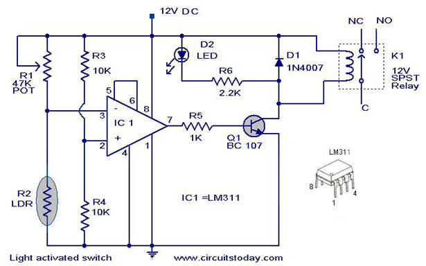
A simple light-activated switch circuit with a diagram and schematic using IC LM311 wired as a voltage comparator and an LDR that acts as a light sensor. The described circuit utilizes the LM311 integrated circuit, which functions as a voltage...
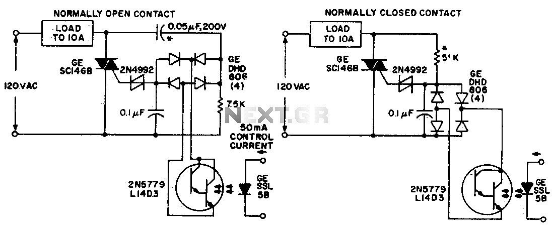
Both circuits utilize the GE SC146B, a 200 V, 10 A Triac for load current contacts. These triacs are activated by standard SBS (2N4992) trigger circuits, which are managed by a photo-Darlington configuration, functioning through the DA806 bridge as...
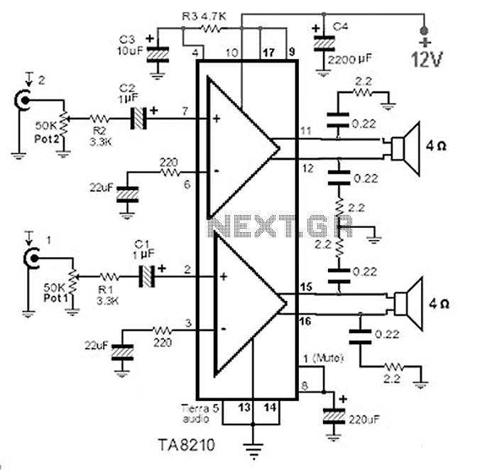
This circuit consists of a 2 x 22 watt BTL amplifier utilizing the IC TA8210AH. It functions not only as an automobile amplifier but is also suitable for low-frequency sound applications, particularly in high-fidelity audio systems, due to its...
A request has been made to automate certain functions within a residence, specifically to control the on and off states of CFL lamps using a triac that is coupled to a logic circuit via a zero-crossing detection mechanism. To achieve...
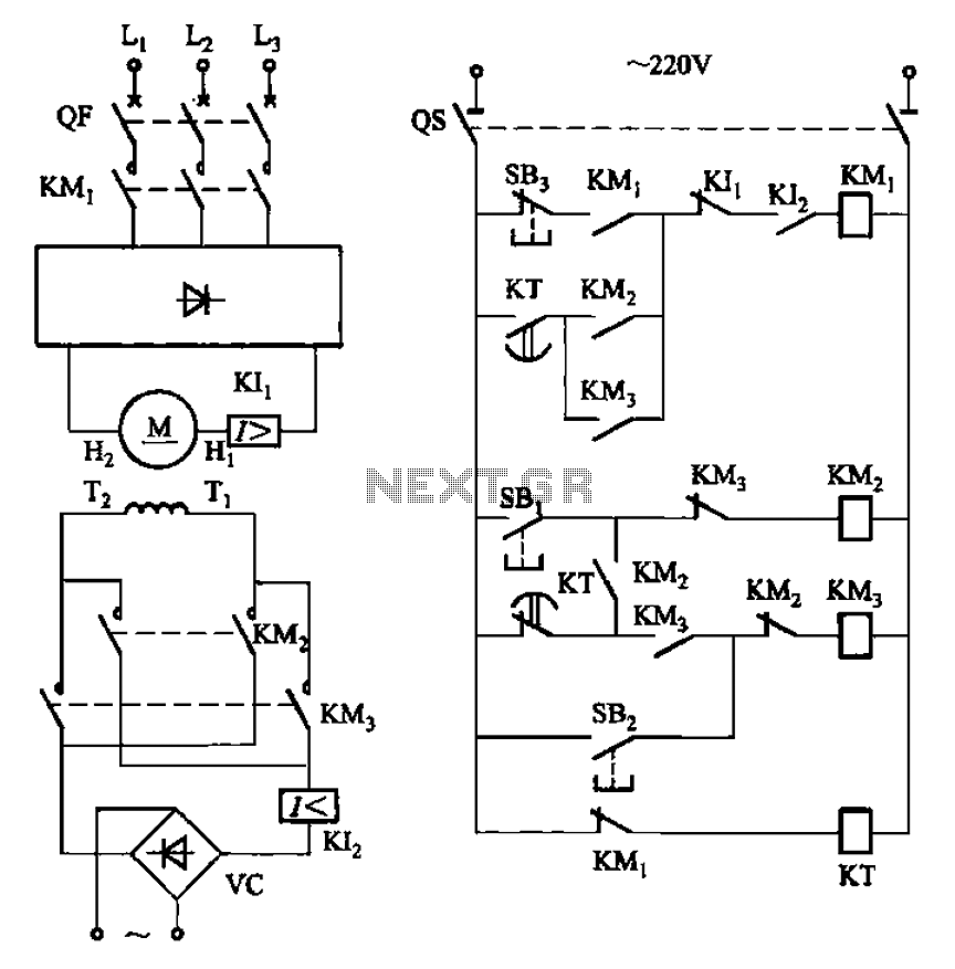
The circuit depicted in Figure 3-193 illustrates a separately excited DC motor. The brake circuit is not activated; therefore, positive reversals occur alternately using a delay action relay, ensuring that the motor reverses direction after coming to a stop. The...
Automatic door control systems typically have a high market price for finished products. The proposed method is suitable for home use, utilizing easily accessible components. This design is ideal for those interested in creating their own automatic door system....