
lie detector circuit diagram
This lie detector circuit is designed to assess physiological responses that may indicate deception. It utilizes two primary physiological metrics: skin resistance and heart rate. The electrodes, positioned on the subject's fingers or wrist, measure variations in skin conductance, which is influenced by sweat production—a common response to stress or anxiety. The circuit's reliance on dual 9-volt batteries ensures stable operation, minimizing the risk of fluctuations that could affect readings.
Operational amplifier A1 serves a dual purpose; it amplifies the changes in voltage corresponding to skin resistance and acts as a signal separator, ensuring that the output is clean and accurate for further processing. The output signal is then directed to a measuring instrument via resistor R3, allowing for real-time monitoring of the subject's emotional state.
Operational amplifier A2 functions as an integrator, smoothing out the fluctuations in skin resistance readings over time. This feature is crucial for distinguishing between normal variations in skin conductance and significant changes that may indicate deceptive behavior. The integration time is adjustable through the combination of R5, C2, and C3, allowing the user to tailor the circuit's responsiveness to the specific characteristics of the subject being tested.
The inclusion of diodes D1 and D3 enhances the circuit's responsiveness, providing immediate feedback during the initial stages of measurement. The potentiometer P1 allows for fine-tuning of the delay before the circuit begins to indicate results, accommodating individual differences in physiological responses.
Adjustability is a key feature of this circuit, particularly with the resistance value of R1. By incorporating a potentiometer in place of R1, the user can calibrate the device for different subjects, ensuring that the lie detector remains sensitive to variations in skin conductance that may arise from individual physiological differences. This adaptability is essential for maintaining the accuracy and reliability of the lie detection process.This lie detector circuit diagram will accord two readings: one for difficult questions for the accountable and addition to appearance its affecting accompaniment in general. The affecting states are detected not alone by affection exhausted accelaration and abashed easily but aswell an access in derma clamminess whose attrition decreases causing
the access into operation of the lie detector. Two electrodes can be acclimated as a adjustable wire, bare, captivated about fingers or wrist. In adjustment to not access the altitude aftereffect the accessory have to be powered from two 9 Volts batteries. Each change in resistance, and accordingly the voltage at the ascribe circuit will be amplified by operational amplifier A1, which aswell serves as separator.
The achievement arresting will determine, by R3, a aberration of the barometer instrument. General affecting accompaniment of a being can be adjourned by barometer the boilerplate attrition of the derma over a aeon of time. The adumbration is provided by an indicator apparatus affiliated to point B of the circuit. Operational amplifier A2 is affiliated as an integrator and allows the circuit to automatically acclimatize according to the boilerplate attrition of the skin.
Length of time to admeasurement the derma attrition is bent by R5, C2 and C3. Until such time elapses, the lie detector gives no adumbration although diodes D1 and D3 accommodate a accelerated acknowledgment of the circuit. Potentiometer P1 allows you to acclimatize the time adjournment of the circuit. Since derma attrition varies from one being to another, may be all-important to change the attrition amount R1.
This attrition can be replaced with a potentiometer. Reading a abundant amount to the apparatus affiliated to the achievement of B indicates that subject`s derma attrition is low (which is a appropriate of humans with adhesive hands) and it is appropriate to abate the amount of R1. 🔗 External reference
Related Circuits
This circuit is designed to demonstrate high frequency and high voltage, capable of producing approximately 30kV, depending on the transformer utilized. It is cost-effective and straightforward to construct, primarily using a standard TV flyback transformer. This circuit can power...
A CI-22BG tube and a CI-3BG tube were purchased for a total of 16G. Due to the lack of radioactive materials for testing the Geiger counter, a piece of radioactive Fiesta dinnerware was ordered from eBay. Red Fiestaware historically...

The transmitter provides an optical link (infrared) for headphones. Three infrared LEDs (IR) are powered by T1, with P1 used to adjust the current level. The current consumption of this headphones infrared transmitter is approximately 60mA at 9V. The infrared...
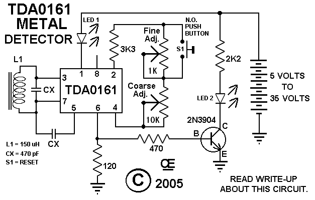
This circuit features an LED indicator with two identical LEDs depicted in the schematic. The modification in Advanced Schematic-2 enhances the detector's sensitivity by incorporating a manual reset function to eliminate the built-in hysteresis of the integrated circuit (IC)....
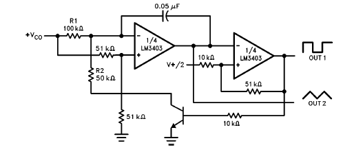
The LM3403 op-amp family includes the LM3303, which is a monolithic quad op-amp known for its high gain. It features a compensated internal frequency, allowing it to operate effectively across a wide range of voltages from both single and...
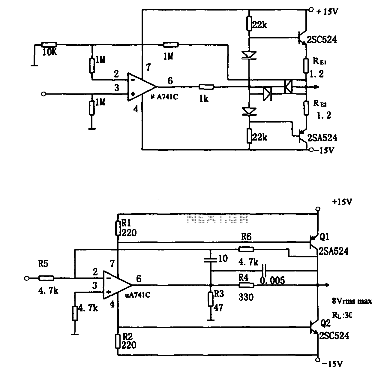
The direct coupling audio power amplifier utilizes an integrated operational amplifier. There are typically two practical configurations. The first configuration, depicted in (a), features a circuit structure that includes the output of the operational amplifier and a complementary symmetry...