
boost converter circuit for digital

The LM2623A is a highly efficient DC-DC converter designed for low-voltage applications, making it well-suited for driving motors in digital cameras. The circuit configuration typically involves a switching regulator topology, which allows for efficient voltage conversion while minimizing power loss. The input voltage range of 1.8 to 4.5 volts is critical, as it accommodates various battery chemistries, including alkaline, nickel-metal hydride (Ni-MH), and lithium-ion (Li-Ion) cells.
The duty cycle of the converter is a crucial parameter that affects both the output voltage and the efficiency of the circuit. At lower input voltages, such as 1.8 volts, a higher duty cycle (86%) is required to maintain the desired output voltage of 5 volts. However, operating at this duty cycle can lead to increased ripple voltage, which may negatively impact the performance of sensitive electronic components, such as those found in digital cameras.
Conversely, at higher input voltages, such as 4.5 volts, the duty cycle decreases to 71%. While this lower duty cycle improves efficiency and reduces ripple, it also limits the output capability of the converter. Therefore, careful consideration must be given to the design parameters to ensure that the circuit meets the operational requirements of the digital camera motor under varying input conditions.
To enhance the performance of this circuit, additional components such as input and output capacitors, inductors, and feedback resistors may be incorporated. Input capacitors help to stabilize the input voltage and reduce voltage spikes, while output capacitors smooth out the voltage delivered to the motor, minimizing ripple. The inductor plays a vital role in energy storage during the switching cycle, and the feedback resistors are essential for regulating the output voltage by providing feedback to the control circuitry.
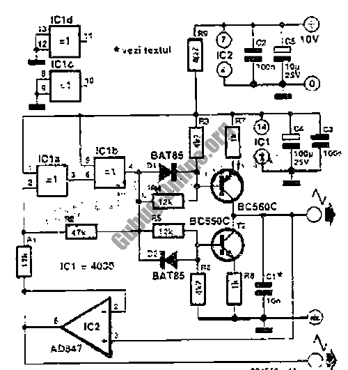
Overall, the LM2623A-based converter circuit is a practical solution for powering digital camera motors, ensuring compatibility with a range of battery types while maintaining efficiency and performance across its specified input voltage range.This is a design circuit for converter that using for a very practical LM2623A ratio adaptive circuit to drive a digital camera motor. It produces 5 volts from input voltages ranging between 1. 8 and 4. 5 volts. This is the figure of the circuit; The duty cycle is not shown, but it varies from about 86% at 1. 8 volts in to 71% at 4. 5 volts in. Mainta ining the 86% duty cycle at 4. 5 volts would reduce the efficiency and increase the ripple. Maintaining the 70% duty cycle at 1. 8 volts would significantly reduce the output capability. Several camera manufacturers are already requiring 1. 8 to 4. 5 volt operation from all the power supplies. The 1. 8 to 4. 5 voltage standard allows a manufacturer to build his product and let the user select disposable Alkalines, Ni-MH or Li-Ion at the point of purchase. 🔗 External reference
Related Circuits
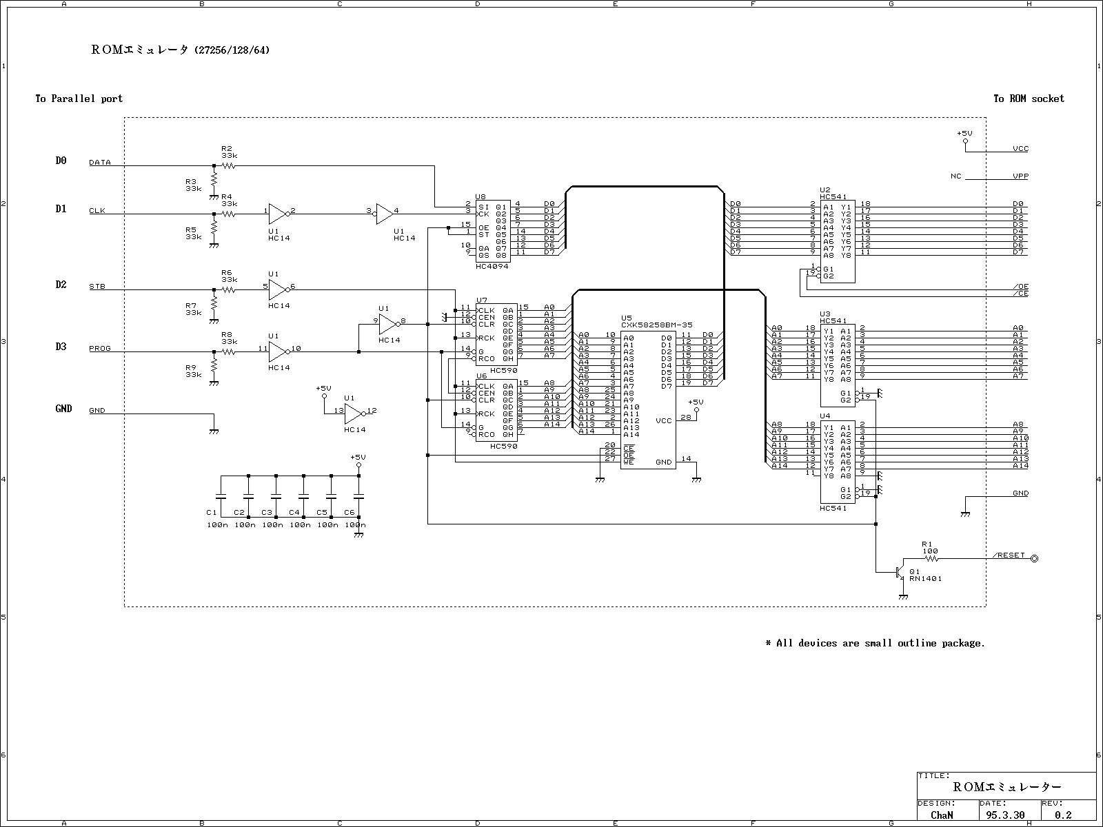
This ROM emulator improves the easiness to build/use it by reducing down its function which can be used as a ROM emulator. The kind of the ROM types to be emulated are 2764, 27128, and 27256. The debugging capability...
Utilizing a dual polarity power supply (+-5V is suitable) can resolve most clipping issues. It is necessary to consult the data sheet for the appropriate pins to connect the voltages. A dual polarity power supply is essential in many electronic...
Individuals who frequently utilize battery-operated devices or require a negative voltage from a single positive source will find the following converter beneficial. This circuit can convert a 9 V positive battery voltage to a negative voltage using the well-known...
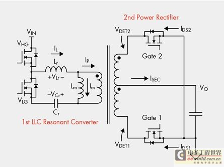
The designer is looking for a solution with higher efficiency and lower power consumption in order to minimize unnecessary energy loss. The approach involves using syntony inductance to harmonize the capacitive LLC syntony converter, employing zero voltage switching (ZVS)...
This design outlines a simple 1 kHz square wave generator utilizing a few components and the LM3909 integrated circuit, which is beneficial for testing audio equipment. The circuit operates on a single 1.5V battery cell, producing a maximum output...
Ultrasonic atomizer circuit: How to generate an atomized water mist using ultrasonic sound waves. The ultrasonic atomizer circuit is designed to produce a fine mist of water by utilizing ultrasonic sound waves. This process involves the conversion of electrical energy...