
digital volume control

A dual polarity power supply is essential in many electronic circuits, particularly in operational amplifier configurations and analog signal processing applications. The use of a +-5V power supply provides a balanced voltage range that allows for both positive and negative signal swings, which is crucial for maintaining signal integrity and minimizing distortion.
In a typical schematic, the power supply connections will be made to specific pins on the integrated circuit (IC) as indicated in the manufacturer's data sheet. These connections are vital for the proper operation of the circuit. The positive voltage will connect to the V+ pin, while the negative voltage will connect to the V- pin. It is important to ensure that these connections are made correctly to avoid damaging the IC.
Additionally, the circuit may include bypass capacitors connected close to the power supply pins to filter out any high-frequency noise that could affect performance. These capacitors help stabilize the voltage levels and improve the overall reliability of the circuit.
When designing the layout, it is advisable to keep the power supply traces short and wide to minimize resistance and inductance, which can lead to voltage drops and unwanted noise. Ground planes should also be considered to provide a common reference point for all components, further enhancing the circuit's performance.
Overall, implementing a dual polarity power supply not only addresses clipping issues but also contributes to the overall robustness and fidelity of the electronic circuit. Proper attention to the details outlined in the data sheet and careful layout considerations will ensure optimal performance.Using a dual polariity power supply (+-5V works fine) will cure most clipping problems. You will have to check the data sheet for the correct pins to connect your voltages. 🔗 External reference
Related Circuits
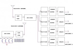
This circuit illustrates a remote control circuit diagram using RF technology without the use of a microcontroller. Features include a simple remote control circuit that operates via radio frequency. The remote control circuit operates by transmitting signals through radio waves,...

The clock displays time in 5-minute intervals, with adjustable hour and minute settings. There is no alarm feature or AM/PM indicator. The clock face is constructed from two pieces of linoleum glued together for added thickness, though floor tiles...
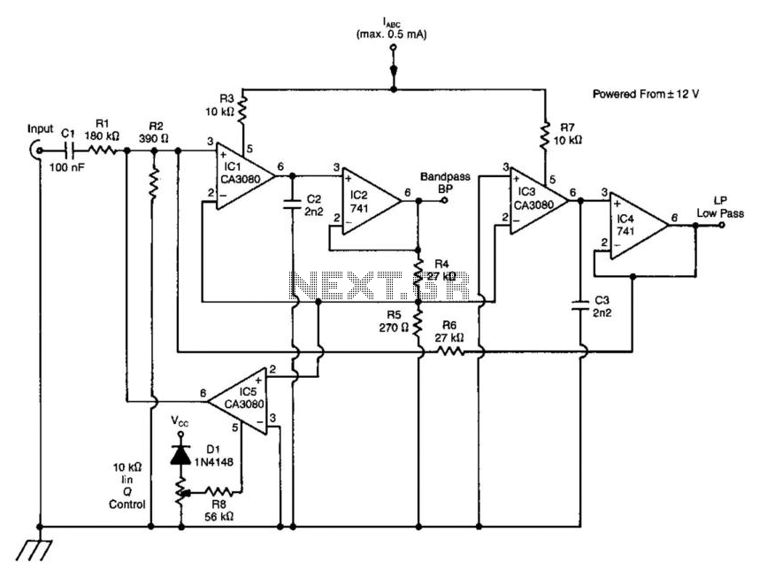
A standard dual integrator filter can be constructed using a few CA3080 operational amplifiers. By varying the parameters L, A, B, and C, the resonant frequency can be swept over a range of 1000:1. At IC1, three current-controlled integrators...
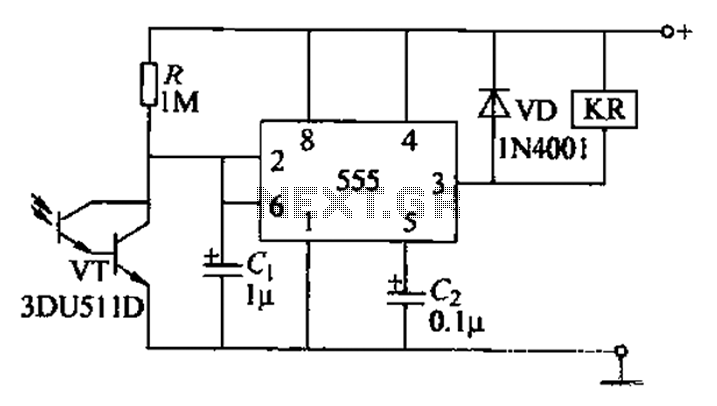
The circuit utilizes a Darlington-type phototransistor as the sensing element, which enhances sensitivity to low light levels, making it suitable for detecting reflected light signals. When the Darlington phototransistor is exposed to light, its resistance decreases, causing the voltage...
The adjustment control for the contrast of an LC-Display typically utilizes a 10-kilohm potentiometer. This arrangement functions adequately, provided that the power supply voltage remains constant. However, in situations where the power supply is variable, such as with a...
The large servos shown alongside a Nokia 3310 mobile phone provide a reference for scale. The servo arms measure 12 cm in length, making them suitable for lifting a bank of solar panels. The local Model Aerodrome in Seaside...