
BQ24105 Switch Mode Lead Acid Battery Charger
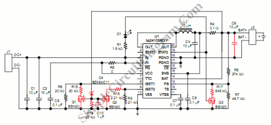
The bq24105 battery charger controller is a highly integrated device that offers a variety of features for charging lithium-based batteries, including power path management, thermal regulation, and programmable charge current. When repurposing this controller for lead acid battery charging, it is essential to implement additional circuitry that can handle the specific charging requirements of lead acid batteries, such as voltage regulation and termination characteristics.
To construct a lead acid battery charger using the bq24105, the following components and configurations are typically necessary:
1. **Power Supply**: A suitable DC power supply that can provide the required input voltage range for the bq24105. The input voltage should be higher than the maximum lead acid battery charging voltage.
2. **External MOSFETs**: The addition of external N-channel MOSFETs may be required to handle the higher current levels associated with lead acid battery charging.
3. **Voltage Divider**: A voltage divider network can be used to sense the battery voltage and provide feedback to the bq24105 to ensure that the charging voltage remains within safe limits for lead acid batteries.
4. **Termination Circuit**: A termination circuit must be designed to stop the charging process once the battery reaches its full charge voltage. This can be accomplished using a comparator circuit that monitors the battery voltage and sends a signal to the bq24105 to cease charging.
5. **Inductor and Capacitors**: The circuit will also require an appropriately rated inductor and output capacitors to smooth the voltage and current during the switching process.
6. **Thermal Management**: Adequate thermal management should be implemented to prevent overheating of components during operation, which may involve the use of heat sinks or thermal pads.
By incorporating these elements, the bq24105 can effectively manage the charging of lead acid batteries, leveraging the efficiency of switch mode power supply technology while accommodating the unique characteristics of lead acid chemistry. The complexity of the circuit design increases due to the need for additional components and careful consideration of charging profiles, but the improved efficiency can result in better performance and longer battery life.Switch mode circuits can implement the lead acid battery charger with a more efficient. It can be constructed using bq24105 battery charger controller. The bq24105 was originally designed to charge single-, two- or three-cell Li-polymer and Li-ion battery packs. The bq24105 doesn`t has a feature to control lead acid battery charger termination. S o external circuitry is added to enable this controller to charge lead acid batteries. Switching mode charging method for lead acid batteries provides high efficiency, although the circuit becomes more complex. Here is the circuit : We aim to transmit more information by carrying articles. Please send us an E-mail to wanghuali@hqew. net within 15 days if we are involved in the problems of article content, copyright or other problems.
We will delete it soon. 🔗 External reference
Related Circuits
Model railroad turnouts, often referred to as switches, can be controlled in various ways. The simplest method is manual control, operated by hand. Remote activation is typically achieved through pneumatic (air) or electrical means. The project discussed in these...
A short-circuit-proof battery charger provides an average charging current of approximately 8 A to a 12-V lead/acid storage battery. The charger circuit has the additional advantage of being unaffected and undamaged by incorrect battery connections. With an input voltage...
The test circuit indicates the remaining capacity of a battery by measuring the duration, in seconds, that an LED remains illuminated after the test switch (S1) is activated. This circuit has demonstrated reliability in testing nickel-cadmium (NiCad), carbon, and...
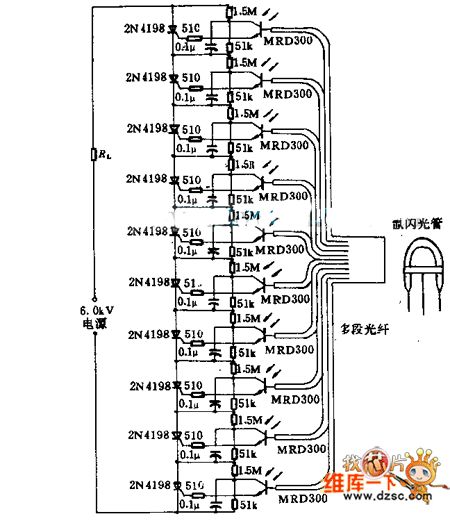
Light emitted by a Xenon flash tube is transmitted to the phototransistor MRD300 through an optical fiber. The sensitive current is amplified to trigger a series of thyristors simultaneously. Consequently, a high voltage of 6000V is applied to loader...
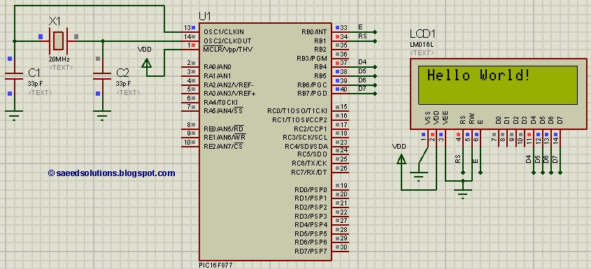
This tutorial on the PIC16F877 microcontroller addresses the question, "How to interface an LCD in 4-bit mode with the PIC16F877?" It also utilizes the PIC16 simulator (Proteus). The PIC16F877 microcontroller is a versatile device widely used in embedded systems. This...
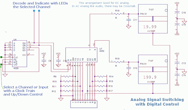
This circuit utilizes a 4052 as a DC Analog Multiplexer. The inputs to this multiplexer must originate from low-impedance output operational amplifiers (OpAmps). The resistors depicted are unnecessary once the signal conditioning OpAmps are connected. However, 100K resistors can...