
pic16f877 lcd interfacing code in 4bit mode and proteus simulation

The PIC16F877 microcontroller is a versatile device widely used in embedded systems. This tutorial focuses on interfacing a Liquid Crystal Display (LCD) in 4-bit mode, which is a common method for reducing the number of data lines required for communication between the microcontroller and the display.
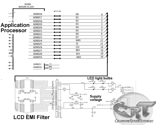
To implement this, the LCD is connected to the PIC16F877 through a series of GPIO (General Purpose Input/Output) pins. In 4-bit mode, only four data lines (D4 to D7) are used for sending data to the LCD, while additional control lines such as RS (Register Select), RW (Read/Write), and E (Enable) are also connected. The RS pin determines whether the data being sent is a command or character, the RW pin indicates the operation mode (read or write), and the E pin is used to latch the data into the LCD.
The tutorial likely includes a schematic diagram illustrating the connections between the PIC16F877 and the LCD, as well as example code to demonstrate how to initialize the LCD, send commands, and display characters. The use of the PIC16 simulator (Proteus) allows for the virtual testing of the circuit before actual implementation, ensuring that the design functions as intended without the need for physical components.
In summary, this tutorial serves as a comprehensive guide for engineers and hobbyists looking to integrate an LCD with the PIC16F877 microcontroller using an efficient 4-bit communication method, while also providing simulation capabilities for testing and validation.This PIC16F877 microcontroller tutorial answers the question, ""How to interface LCD in 4bit mode with PIC16F877"" ? Also, using PIC16 simulator (Proteus) y.. 🔗 External reference
Related Circuits
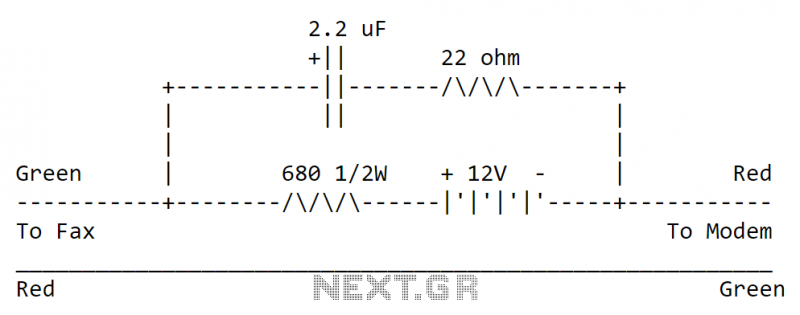
The circuit can be easily built to a small plastic box with telephone connectors in both ends. The circuit takes about 10-20 mA current, so if the circuit is not in use all the time it is best to...
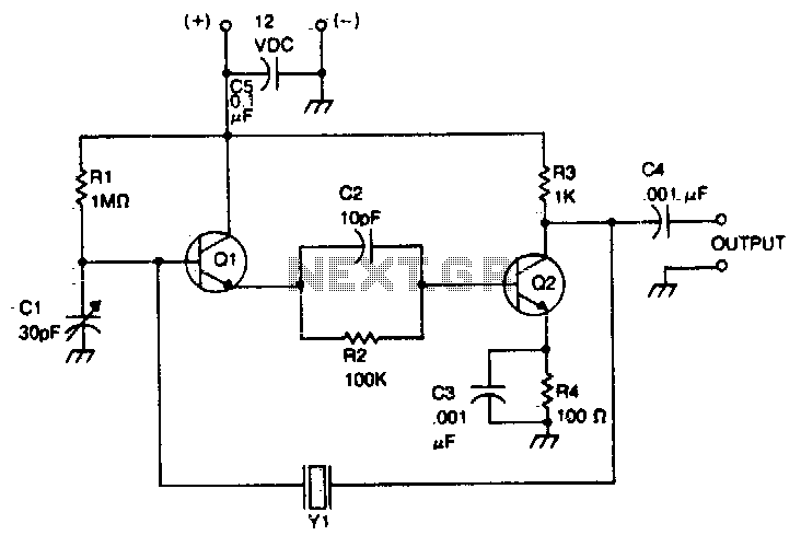
The crystal is positioned between the collector of the output stage and the base of the input stage. The oscillation frequency can be accurately adjusted using the trimmer capacitor CI. This circuit operates within a frequency range of 500...
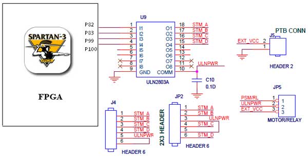
The Spartan-3 Primer board features external stepper motor interfacing, as illustrated in the accompanying figure. The stepper motor is driven by a ULN2803A, which is a high-voltage, high-current Darlington transistor array. The ULN2803 is utilized as a driver for...
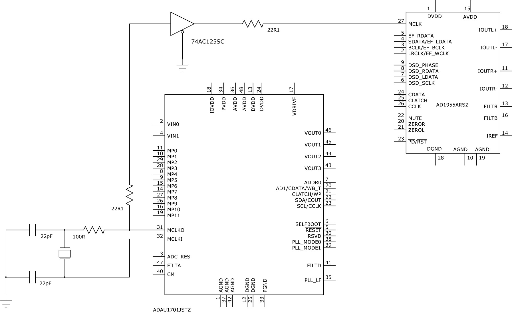
The ADAU1701 datasheet recommends on page 18 that MP11 should be used to derive MCLK. Additionally, MP11 also serves the purpose of OUTPUT_BCLK when used for I2S. This raises the question of whether MCLK and BCLK can be connected...
An LCD (liquid crystal display) is an electronically modulated optical device composed of multiple pixels filled with liquid crystals, arranged in front of a light source (backlight) or reflector to generate images in either color or monochrome. The block...
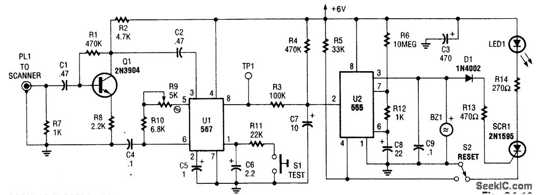
This circuit detects the 1050 Hz tone transmitted by NOAA (National Oceanic and Atmospheric Administration) Weather radio stations that operate within the frequency range of 162.40 to 162.55 MHz. The tone lasts for several seconds. Q1 serves as an...