
Bridge amplifier

This low voltage high power output circuit is primarily utilized in applications where efficient power delivery is crucial, such as in audio amplification or driving low impedance loads. The circuit operates effectively at voltages of 6 V and 12 V, providing adequate power levels while maintaining low distortion and high fidelity.
The design eliminates the need for coupling capacitors, which simplifies the circuit and reduces component count. This feature is particularly advantageous in applications where space and weight are critical, such as portable devices. The close matching of output DC levels minimizes the risk of DC offset, which can adversely affect performance and lead to potential damage in sensitive components.
The inclusion of a 500 K potentiometer allows for fine-tuning of the circuit. By adjusting this potentiometer, the user can achieve precise matching of output characteristics and eliminate any DC current that may flow through the load. This adjustment capability enhances the circuit's versatility, making it suitable for a wide range of applications requiring different load conditions.
Overall, the circuit's design emphasizes simplicity, efficiency, and adaptability, making it an ideal choice for low voltage, high power output applications. Proper implementation of this circuit can lead to significant improvements in performance and reliability in various electronic systems.This circuit is for low voltage applications requiring high power outputs. Output power levels of LO W into 4 ohm from 6 V and 3 V into 8 ohm from 12 V are typical. Coupling capacitors are not necessary since the output dc levels will-be within a few tenths of a volt of each other Where critical matching is required the 500 K potentiometer is added and adjusted for zero dc current flow through the load.
Related Circuits
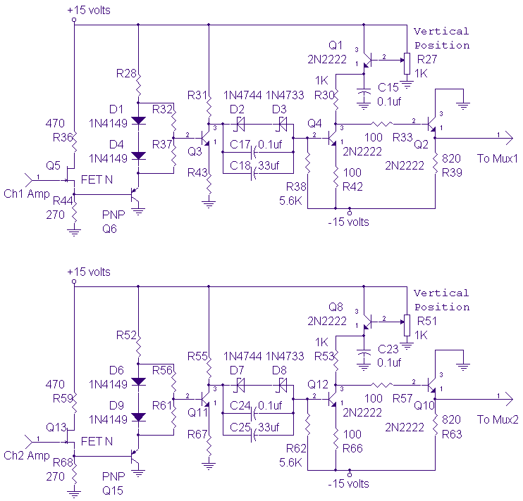
The DC-10 MHz amplifier shown below is identical for both scope channels. The input FET should be mounted directly on the adjustable attenuator switch for best frequency response. The vertical position pots, R27 and R51, change the dc level...
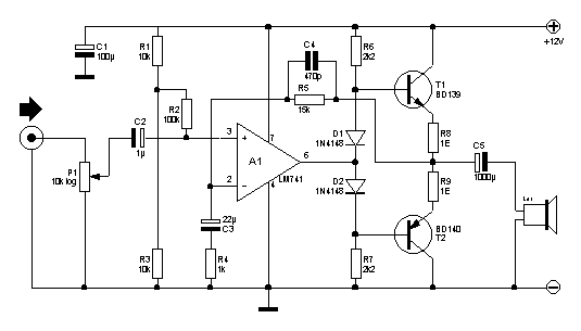
Here you will find a design for a headphone amplifier. The supply voltage is 12 volts. I have the circuit taken as 5 watt amplifier, but after a test showed that with a little speaker to the amplifier power...
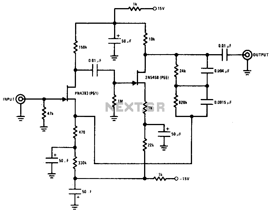
This preamplifier offers a loading ratio of better than -70 dB (referenced to a 10-ohm reluctance phono cartridge) and accepts millivolt input at 1 kHz. It has a dynamic range of approximately 35 dB of gain at 1 kHz...
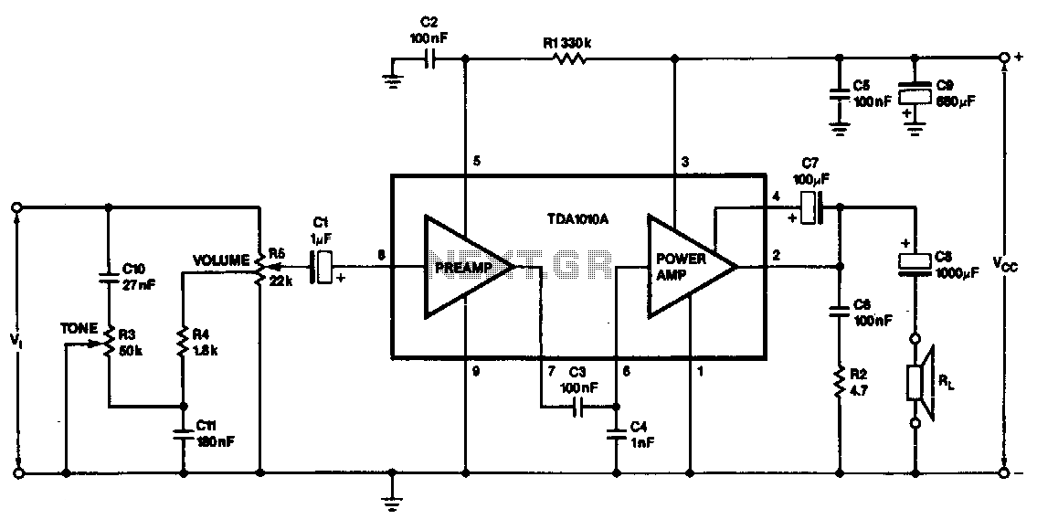
This monolithic IC, class-B audio amplifier circuit is a 6-W car radio amplifier for use with 4-ohm and 2-ohm load impedances. The monolithic integrated circuit (IC) described is designed to function as a Class-B audio amplifier, specifically tailored for...
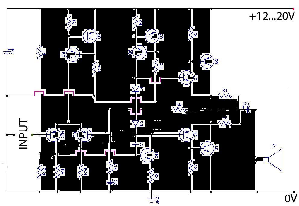
This is a Class AB transistor power amplifier. It is straightforward to construct, utilizing standard components, and is known for its stability and reliability. The entire circuit employs commonly available parts and can be easily assembled on a general-purpose...
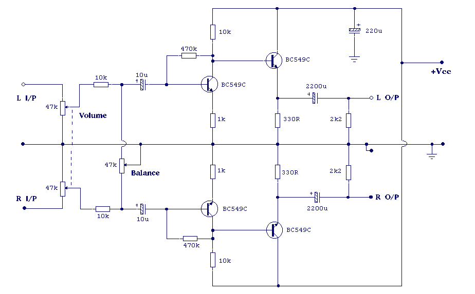
Both halves of the circuit are identical. Both inputs have a dc path to ground via the input 47k control which should be a dual log type potentiometer. The balance control is a single 47k linear potentiometer, which at...