
Stereo Headphone Amplifier
The circuit described is a typical audio signal processing configuration, employing both a balance control and amplification stages to manage stereo audio signals effectively. The dual log potentiometer serves as the input control, allowing for fine-tuning of the audio levels for each channel. This control is critical for achieving a balanced sound output, particularly in stereo applications, where discrepancies between left and right audio signals can lead to an unbalanced listening experience.
The balance control is implemented using a 47k linear potentiometer positioned centrally to ensure equal attenuation of both channels. As the control is adjusted towards one side, it modifies the resistance in the corresponding channel more significantly than in the opposite channel, effectively allowing users to emphasize one channel over the other as needed. This functionality is essential in environments where audio sources may not be perfectly balanced.
The inclusion of 10k resistors preceding the inputs is a protective measure that prevents direct shorting of the inputs to ground, thus safeguarding the circuit from potential damage and ensuring reliable operation. This configuration allows for a stable reference point for the inputs, maintaining integrity in the audio signal path.
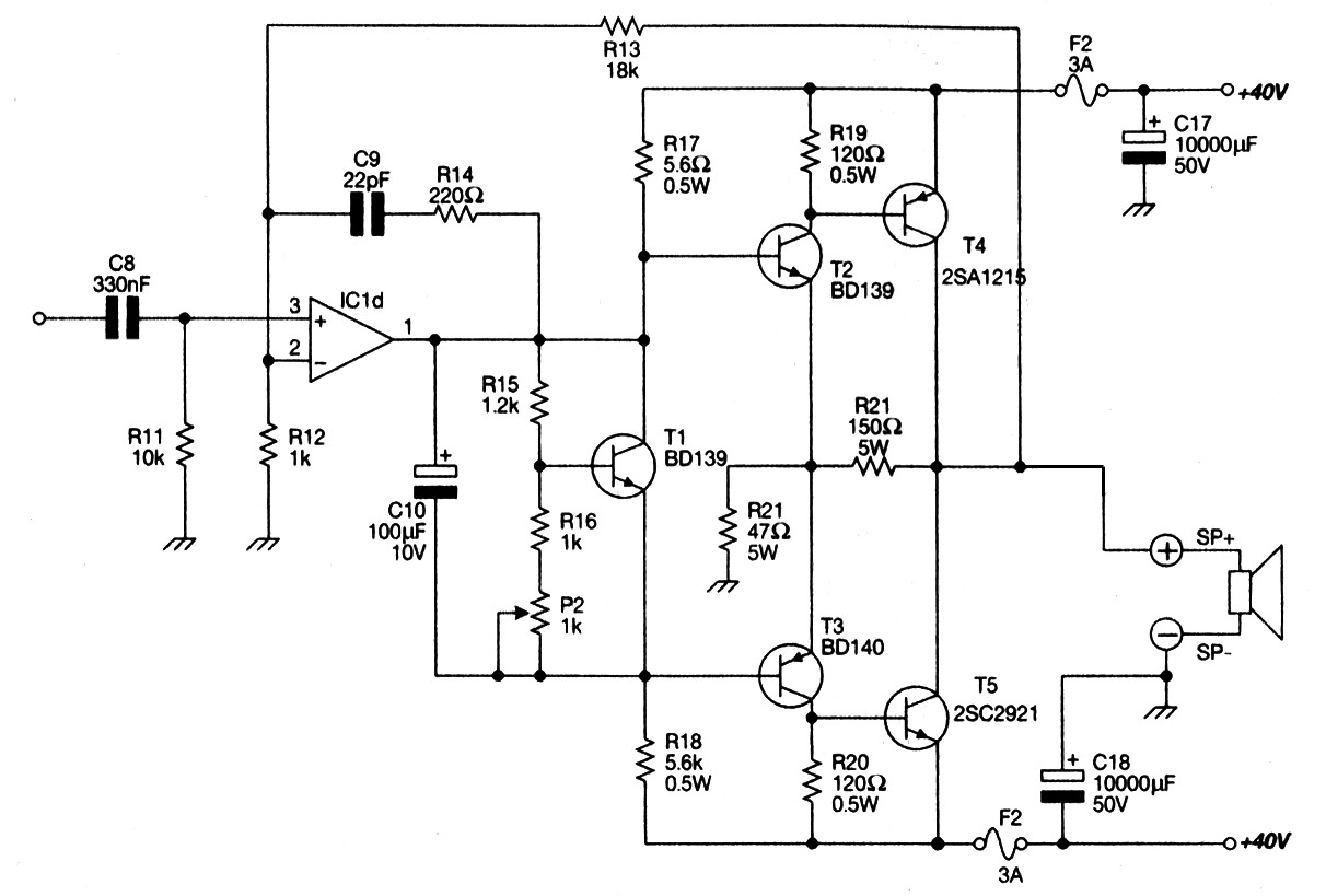
The amplification stage consists of a single-stage common emitter amplifier, which is a standard configuration known for its ability to provide significant voltage gain. This stage is followed by a direct-coupled emitter follower, which serves as a buffer to drive low-impedance loads, such as 8-ohm headphones. The overall gain of the circuit is designed to be less than 10, providing sufficient amplification while maintaining audio fidelity.
The emitter follower configuration is particularly advantageous for driving headphones, as it can deliver the necessary current without introducing distortion, making it suitable for high-quality audio applications. The circuit is optimized for high-performance audio output, ensuring that users can enjoy a clear and balanced sound experience.Both halves of the circuit are identical. Both inputs have a dc path to ground via the input 47k control which should be a dual log type potentiometer. The balance control is a single 47k linear potentiometer, which at center adjustment prevents even attenuation to both left and right input signals.
If the balance control is moved towards the left side, the left input track has less resistance than the right track and the left channel is reduced more than the right side and vice versa. The preceding 10k resitors ensure that neither input can be "shorted" to earth. Amplification of the audio signal is provided by a single stage common emitter amplifier and then via a direct coupled emitter follower. Overall gain is less than 10 but the final emitter follower stage will directly drive 8 ohm headphones.
Higher impedan 🔗 External reference
Related Circuits
12W Audio Power Amplifier Circuit Diagram. Features: small power amplifier, excellent sound quality, incorporates a fully integrated design. The 12W audio power amplifier circuit is designed to provide high-quality audio amplification in a compact form factor. This amplifier is capable...
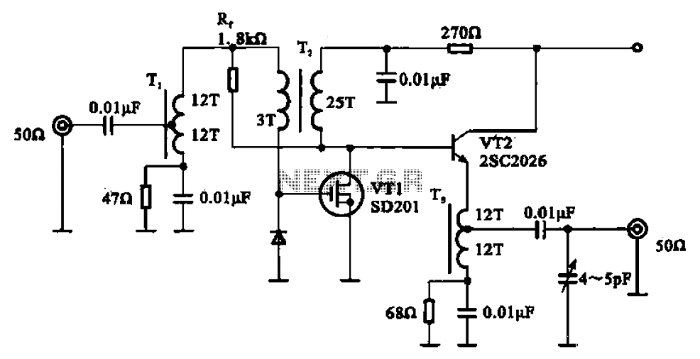
A broadband amplifier circuit utilizing a negative feedback amplifier configuration is presented. This circuit employs transformer coupling and a combination of amplifying sections and field-effect transistors (FETs). The input signal is applied to the center tap of the transformer...
A buffer amplifier is necessary for a typical pH probe to isolate its source resistance, which ranges from 10^6 to 10^9 ohms, from the external circuitry. Such an amplifier is illustrated in the... The buffer amplifier serves a critical role...
Main Power Amplifier OCL 100 watt using MJ802 and MJ4502 transistors. It is designed to provide strong bass and bold treble, making it suitable for various applications such as parties or home theater systems. This Class AB amplifier delivers...
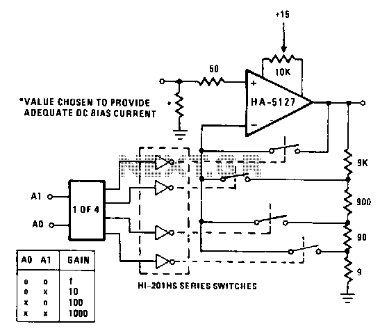
A circuit may often be required to perform multiple functions. In these cases, the variable gain configuration of the circuit can be particularly advantageous. This programmable gain stage utilizes CMOS analog switches to modify the feedback amount, thereby adjusting...
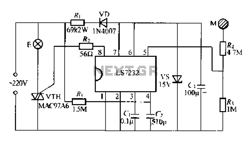
Figure (a) illustrates a general inverting amplifier circuit, which includes a 100k potentiometer as a feedback resistor connected in series between the input terminal and the inverting input to compensate for the DC bias current. The potentiometer (Rp) should...
Warning: include(partials/cookie-banner.php): Failed to open stream: Permission denied in /var/www/html/nextgr/view-circuit.php on line 713
Warning: include(): Failed opening 'partials/cookie-banner.php' for inclusion (include_path='.:/usr/share/php') in /var/www/html/nextgr/view-circuit.php on line 713