
Brightness controller for low power lamps
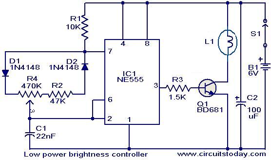
The circuit employs the NE555 timer IC, which is a versatile component widely used in various applications. In this configuration, the NE555 operates as an astable multivibrator, generating a continuous square wave output. This output toggles between high and low states, with the duty cycle determining the proportion of time the output remains high. By adjusting the resistance of potentiometer R4, the duty cycle can be varied, which in turn modulates the average voltage applied to the load, resulting in a change in brightness for the incandescent lamp.
Transistor Q1 acts as a switch that controls the current flowing through the lamp. When the output of the NE555 is high, Q1 is turned on, allowing current to flow through the lamp, thus illuminating it. Conversely, when the output is low, Q1 turns off, cutting off the current and extinguishing the lamp. The effective brightness is directly proportional to the duty cycle; a higher duty cycle results in a brighter lamp, while a lower duty cycle leads to dimmer illumination.
This circuit's design can be easily adapted for other applications, such as controlling the speed of small DC motors. In this case, the same principles apply, where the average voltage delivered to the motor is controlled by adjusting the duty cycle of the NE555 output. By varying the duty cycle, the motor speed can be finely tuned, providing a practical solution for applications requiring speed control. Overall, this circuit exemplifies a straightforward yet effective method for managing the brightness of lamps and the speed of motors using minimal components.The circuit given here can be used to control the brightness of low power incandescent lamps. The circuit is based on IC NE555 which is wired as an astable multivibrator with variable duty cycle. The output of IC is connected to the base of transistor Q1. The Q1 drives the lamp. The duty cycle of the multivibrator can be varied by varying the POT R 4. As a result, the brightness of the lamp varies according to the position of the POT R4. The same circuit can be also used for speed control of small DC motors. 🔗 External reference
Related Circuits
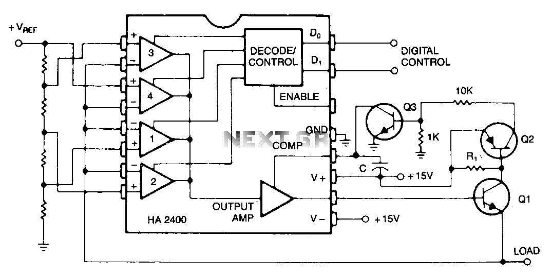
Many systems require one or more relatively low-current voltage sources that can be programmed to a few predetermined levels. The circuit presented generates positive output levels but can be modified for negative or bipolar outputs. Q1 serves as the...

This circuit utilizes a comparator configured as a Schmitt trigger (311H) along with two active bandpass filters (LM318H) to achieve a 3-kHz output. Higher odd harmonics can be generated by adjusting the active filters to the desired frequency, such...
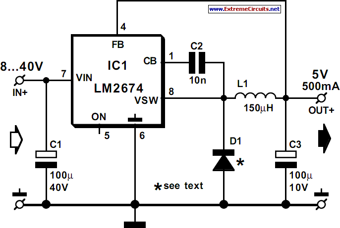
National Semiconductor has been designing and manufacturing integrated circuits (ICs) for switch-mode power supplies for many years. The application of these devices is typically straightforward, supported by comprehensive documentation. A common example of a switch-mode power supply is based...
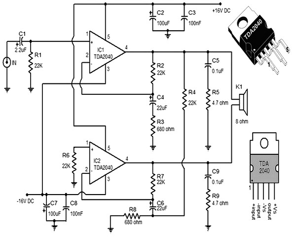
This small and compact stereo amplifier is powerful and can easily replace a broken amplifier or be used in new constructions, or to create an active speaker, when combined with a preamplifier. Its remarkable features make it a true...
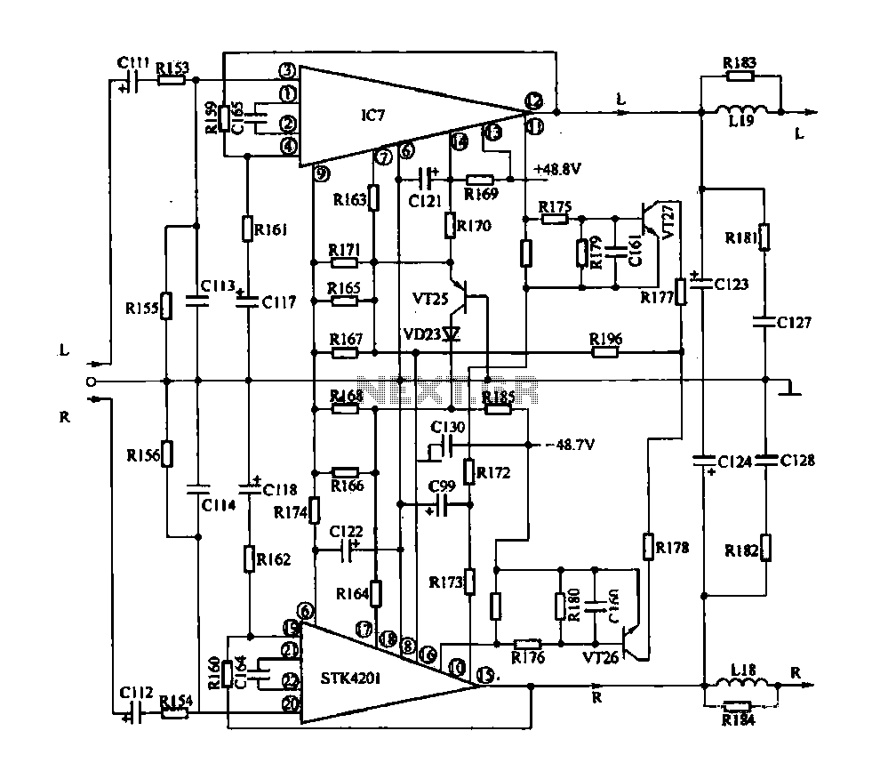
The rapid advancement of integrated circuit technology has led to the widespread emergence of integrated circuit amplifiers. These amplifiers exhibit high levels of technology and performance indicators. Their advantages include compact size, simplified circuitry, exceptional performance, and comprehensive protection...
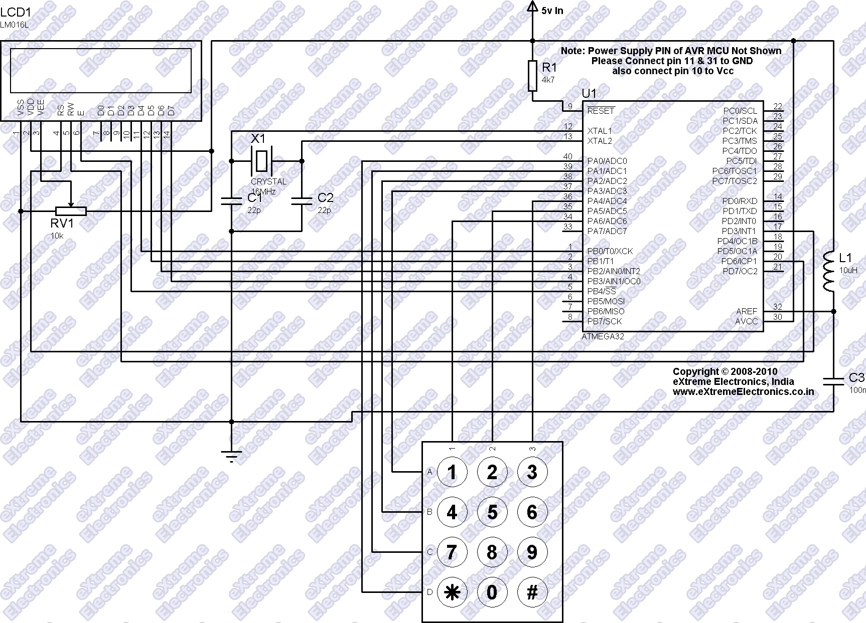
Many applications require a large number of keys connected to a computing system. Examples include PC keyboards, cell phone keypads, and calculators. Connecting a single key to a microcontroller unit (MCU) is straightforward; however, connecting 10 or 100 keys...