
4x3 4x4 Matrix Keypad Interface with Atmel AVR Microcontrollers

The technique is known as a multiplexed matrix keypad. In this approach, keys are arranged in a matrix format (row/column). The rows R0 to R3 are connected to the input lines of the microcontroller. The I/O pins connected to the rows are configured as inputs by setting the appropriate data direction register (DDR) in AVR and TRIS register in PIC microcontrollers. The columns C0 to C3 are also connected to the MCU's I/O lines and are maintained in a high impedance state (also referred to as input). In this high impedance state, the pins are neither HIGH nor LOW; they are in a tri-state condition. The PORT value for these pins is set to low, which allows them to become outputs with a low value once their DDR bits are set to 1.
For instance, if C0 is set to LOW while all other columns are in a high impedance state, the status of rows R0 to R3 can be read to determine which keys are pressed. If the rows read HIGH, it indicates that the button is not pressed. Internal pull-up resistors are enabled on the rows to maintain a HIGH state when they are floating (not connected). When a key is pressed, it connects the row to the LOW line from the column, resulting in a LOW reading. The process is repeated by setting C0 back to high impedance and making C1 LOW to read the status of the second column of keys. This scanning continues for all columns.
The PORTA driver operates such that when a bit is set to 1, it appears as HIGH (5V), but this only applies if that bit is configured as an output. If it is set as an input, setting a bit to 1 activates the internal pull-up for that bit. The DDRA data direction register is used to designate any pin on that port as either input or output. A bit value of 1 indicates output, while a value of 0 indicates input. The input state is also referred to as tri-state or high impedance.
When selecting a column, for example, C0, it is set to LOW (GND or logic 0), while all other columns are set to high impedance (input). It is essential to keep other lines in high impedance to prevent them from being in output mode, which would require them to be either LOW or HIGH. Only one column can be LOW at a time, so all other columns must remain HIGH. This is illustrated in the accompanying figure, where the red color indicates a high state and green indicates a low state. Maintaining other columns in a high impedance state prevents current from flowing to GND through the selected column.
The program can be implemented to learn the use of a multiplexed 4x3 keypad with an AVR microcontroller. Specific skills required include familiarity with AVR GPIO details, LCD library usage, and bit operations in C. General skills needed encompass setting up and using AVR Studio and avr-gcc.
The hardware setup includes an ATmega32 microcontroller operating at 16MHz with an external crystal. The fuse byte settings are HIGH = C9 and LOW = FF, which are crucial for proper operation.
For the LCD to AVR connection, the following connections are made:
- VSS to GND
- VDD to +5V
- VEE to the center pin of a 10K potentiometer (the other two pins connected to +5V and GND)
- Adjust the potentiometer until a clear text display is achieved.
- RS to PD3
- RW to PD6
- E to PB4
- Data lines DB4 to DB7 connected to PB0 to PB3 respectively.
- An LED is connected with the positive terminal to +5V via a 100-ohm resistor and the negative terminal to GND.
For the keypad connections:
- COL1 to PA6
- COL2 to PA5
- COL3 to PA4
- ROW1 to PA3
- ROW2 to PA2
- ROW3 to PA1
- ROW4 to PA0Many application requires large number of keys connected to a computing system. Example includes a PC keyboard, Cell Phone keypad and Calculators. If we connect a single key to MCU, we just connect it directly to i/o line. But we cannot connect, say 10 or 100 keys directly MCUs i/o. Because :- We want to avoid all these troubles so we use some clever technique. The technique is called multiplexed matrix keypad. In this technique keys are connected in a matrix (row/column) style as shown below. The rows R0 to R3 are connected to Input lines of Microcontroller. The i/o pins where they are connected are made Input. This is done by setting the proper DDR Register in AVR and TRIS Register in PIC. The column C0 to C3 are also connected to MCUs i/o line. These are kept at High Impedance State (AKA input), in high z state (z= impedance) state these pins are neither HIGH or LOW they are in TRISTATE. And in their PORT value we set them all as low, so as soon as we change their DDR bit to 1 they become output with value LOW.
As you can see in the image above C0 is made LOW while all other Columns are in HIGH Z State. We can read the Value of R0 to R3 to get their pressed status. If they are high the button is NOT pressed. As we have enabled internal pullups on them, these pullups keep their value high when they are floating (that means NOT connected to anything). But when a key is pressed it is connected to LOW line from the column thus making it LOW. After that we make the C0 High Z again and make C1 LOW. And read R0 to R3 again. This gives us status of the second column of keys. Similarly we scan all columns. PORTA Port Driver - when any bit is set to 1 it appears as HIGH i. e. 5v. But this is the case only if that bit is OUTPUT. If it is input, setting any bit to 1 enables the internal pullup on that bit. DDRA DATA DIRECTION REGISTER - Make any pin on than port as IN or OUT. When bit is 1 it represents Output. When bit is 0 it represents Input. Input state is also called tristate or high Z state. Lets say we selected column number C0, so we make it LOW(i. e. GND or logic 0), in the same time we make all other columns high impedance (i. e. input). If we don`t make other lines high impedance (tristate or Input) they are in output mode. And in output mode they must be either LOW(GND or logic 0) or HIGH (5v or logic 1). We can`t make other lines LOW as we can select only one line at a time and C0 is already low as per assumption.
So the only other possible state is all other columns are HIGH. This is shown in figure below. Red colour on column indicate high state while green is for low state. That`s why all other columns are kept at tristate(neither LOW nor HIGH) but very high input impedance that prevent either source or sink of current from them. So if we kept C1 at high impedance state it wont allow current to flow to GND on C0. 1 / <7465> * 2 3 Program to learn the use of Multiplexed 4x3 keypad with AVR Microcontroller. 4 5 Specific Skills Required 6 >> AVR GPIO details. ( 7 >> LCD Library. ( 8 >> Operations on bits using C. ( 9 10 11 General Skills Required 12 >> AVR Studio Setup and use. ( 13 >> avr-gcc setup and use. 14 15 16 Hardware 17 - 18 ATmega32 @ 16MHz external crystal. 19 Fuse Byte setting HIGH = C9 and LOW = FF (MOST IMP. ) 20 21 22 LCD <-> AVR Connection 23 24 VSS ->GND 25 VDD ->+5V 26 VEE -> CENTER PIN OF 10K POT (OTHER TWO PIN OF POT TO +5V AND GND) 27 ADJ.
THE POT UNTIL YOU HAVE A CLEAR TEXT DISPLAY. 28 29 RS -> PD3 30 RW -> PD6 31 E -> PB4 32 33 DB0 -> N/C 34 DB1 -> N/C 35 DB2 -> N/C 36 DB3 -> N/C 37 38 DB4 -> PB0 39 DB5 -> PB1 40 DB6 -> PB2 41 DB7 -> PB3 42 43 LED+ ->+5V (VIA 100 OHM RES) 44 LED- ->GND 45 46 KEYPAD 47 48 COL1 -> PA6 49 COL2 -> PA5 50 COL3 -> PA4 51 52 ROW1 -> PA3 53 ROW2 -> PA2 54 ROW3 -> PA1 55 ROW4 -> PA0 56 57 NOTICE 58 - 59 NO PART OF THIS WORK CAN BE COPIED, DISTRIBUTED OR PUBLISHED WITHOUT A 60 WRITTEN PERMISSION FROM EXTREME ELECT 🔗 External reference
Related Circuits
The primary advantage of this programmer is its capability to safeguard both the target device and the PC from unexpected voltages when either side is powered down. The buffers utilized are open-drain, with each buffer connected to the Vcc...

Works on AVR controllers with RAM and a hardware UART. This code is easily modified to integrate with ROM applications to provide the ability to monitor and interact with ROM applications via a terminal simulation program over an RS-232...
Atmel Flash devices are well-suited for development due to their ease and speed of reprogramming. They provide ample code space for applications, especially for projects involving the 89Cxx series with the C programming language. Atmel offers a wide selection...
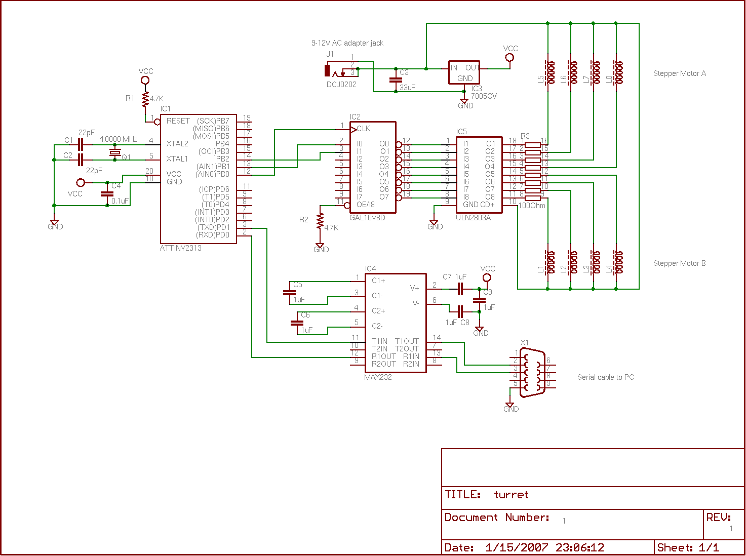
A tiny speedometer/trip computer was constructed using an Atmel ATTiny2313 microcontroller and an HD44780-compatible character LCD display, along with a reed switch and magnets. This device measured the speed of a soapbox derby cart by attaching a permanent magnet...
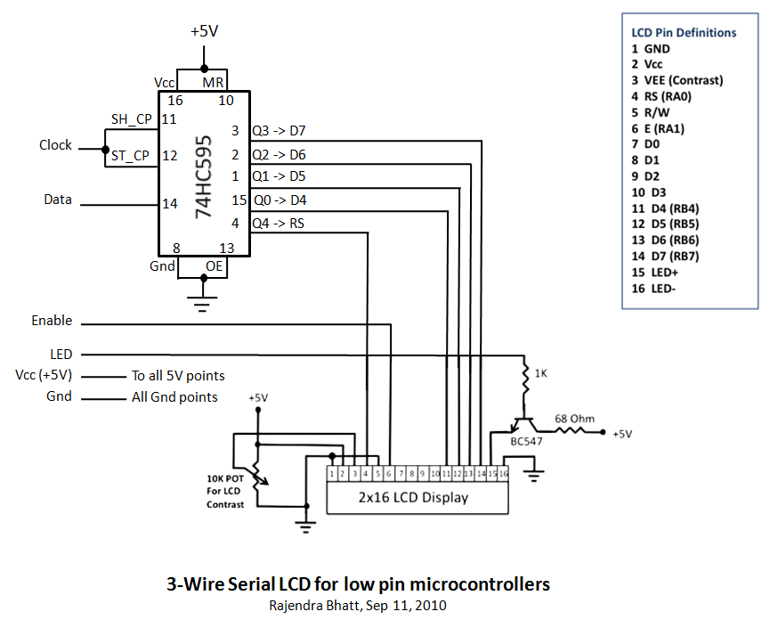
Library routines for a 3-wire LCD interface utilizing the 74HC595 shift register. Additional details can be found in the attached ReadMe document or on the associated webpage. The library routines for the 3-wire LCD interface are designed to facilitate communication...
A circuit for isolating a variable resistor is presented. An optoisolator, which consists of an LED and a photo-conductive cell (or photoresistor), is utilized. The current flowing through the LED regulates its brightness, which subsequently dictates the resistance between...