
british police car siren circuit
The described circuit utilizes two 555 timer ICs, which are versatile components widely used in various electronic applications. The first 555 timer, configured as an astable multivibrator, generates a continuous square wave output at 1 Hz. This low frequency serves as a control signal that modulates the second 555 timer's frequency, which is set up to function as an alarm sound generator.
The second 555 timer is configured in a mode that allows it to produce sound frequencies, specifically alternating between 440 Hz and 550 Hz. The modulation effect is achieved by having the output of the first timer directly influence the timing components of the second timer, effectively changing its duty cycle and frequency in response to the 1 Hz signal.
In this circuit, the transistor 2N3055 plays a crucial role in amplifying the audio output generated by the second 555 timer. The 2N3055 is a power transistor capable of handling high current loads, making it ideal for driving a loudspeaker. The output from the second timer is fed into the base of the 2N3055, which allows it to control a larger current flowing through the loudspeaker, resulting in a louder sound output.
This circuit design is particularly beneficial for beginners in electronics, as it provides a practical application of timer ICs, frequency modulation, and audio amplification. It offers a straightforward project that helps users understand the fundamental principles of sound generation and signal modulation while also allowing for experimentation with component values to modify the sound characteristics.The 555 on the right is wired as an alarm sound generator and the second 555 timer on the left is a 1 Hz astable multivibrator. The output of the left timer is to modulate the frequency of the right timer. This process will cause the right timers frequency to alternate between 440Hz and 550Hz at a 1 Hz cyclic rate.
The transistor 2N3055 is used to amplify the sound signal to the loudspeaker. This circuit should be nice for newbie hobbysts. 🔗 External reference
Related Circuits
This is a game timer circuit diagram. When the game timer is reset, two actions must occur: the 4017 counter must return to zero, and the 4060... The game timer circuit utilizes the 4017 decade counter and the 4060 binary...
This is a very simple project using a printed circuit board and 8 components. It will flash an ordinary 3mm or 5mm (1/8" or 1/4") LED at a rate of about one flash per second. This circuit works on...
This circuit is designed for children's entertainment and is suitable for installation on bicycles, battery-powered cars, motorcycles, as well as in models and other games. When switch SW1 is positioned as indicated in the circuit diagram, it produces the...
This article explains the principle of the Audison LR604XR amplifier. The principle is straightforward; it is recommended to combine the text with a careful reading of the complete schematic. To fully understand this principle, it is advisable to review...
Electrical signals travel along the neurons in the brain and body, continuously transmitting information throughout the complex system. Without these signals, the body would function like a plant, with different parts unaware of each other's conditions, making animal life...
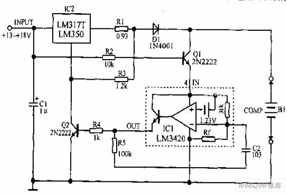
A lithium-ion battery charging circuit is illustrated above. Initially, when charging begins, if the battery voltage is below 8.4V, the output of IC1 is inactive. As a result, Q2 remains off, and the LM317 operates in constant current mode....