
LED Flashing circuits
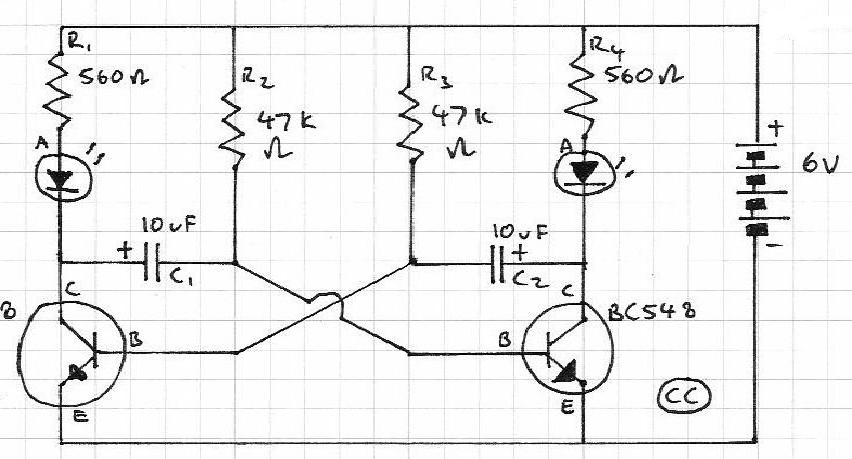
The described circuit utilizes a simple configuration involving a printed circuit board (PCB) and eight components to create a flashing LED effect. The key components include two transistors, a high-value resistor, an electrolytic capacitor, and an LED. The operation of the circuit is predicated on the principle of a high-gain amplifier being driven into saturation, which is a state where the transistor is fully turned on, allowing maximum current to flow through the collector-emitter path.
Upon connecting the power supply, both transistors remain in the off state initially. The charging of the electrolytic capacitor occurs through a 330k ohm resistor and a 22 ohm resistor. This charging process is crucial as it gradually raises the voltage at the base of the first transistor (Q1). Once the base voltage reaches approximately 0.6 volts, Q1 begins to conduct. The conduction of Q1 significantly reduces the resistance between its collector and emitter, allowing a larger current to flow through the circuit.
The LED flashes at a rate of approximately one second, which is determined by the time constant of the charging and discharging cycles of the capacitor in conjunction with the resistors. The design ensures that the energy stored in the electrolytic capacitor is released effectively to produce a visible flash from the LED. The circuit's simplicity makes it an excellent project for beginners in electronics, demonstrating fundamental concepts such as transistor operation, charging and discharging of capacitors, and the use of resistors to control current flow. Overall, this project serves as an educational tool to illustrate basic electronic principles and the functionality of simple circuits.This is a very simple project using a printed circuit board and 8 components. It will flash an ordinary 3mm or 5mm (1/8" or 1/4") LED at a rate of about one flash per second. This circuit works on the basis of a high-gain amplifier being driven into saturation (fully turned-on), firstly by the very small amount of current delivered by a high-value resistor and then from energy stored in an electrolytic. When the supply is connected, both transistors are off and the electrolytic charges via the 330k resistor and 22R. When the voltage on the base of Q1 rises to about .6v, the transistor begins to turn on and the resistance between its collector-emitter ter
🔗 External reference
Related Circuits

This design circuit for audio amplifiers with DC coupling to the load is not commonly used today, despite its clear advantages. One advantage is the elimination of the need for a second (symmetric) power supply, and another is the...

The article explains a straightforward method for creating an incremental LED bar graph using the IC 4017, which has specifications that may not fully align with current requirements. It discusses how to modify the IC for these operations. The...
The AM transmitter circuit consists of an audio amplifier and an RF oscillator. The oscillator is constructed around transistor Q1 and its associated components. The tank circuit, which includes inductor L1 and variable capacitor VC1, is tunable from approximately...
The drawback of the circuit mentioned is that the operational amplifier (op-amp) supply is connected to the high voltage (HV) supply. Most op-amps are limited to approximately 30V for their supply voltage, which prevents the circuit from functioning with...
Blinks 2 LEDs in sequence. An explanation of its operation is requested. It is understood that a capacitor charges, causing the LED to turn off, and when it discharges, the LED turns on. However, clarification on the purpose of...
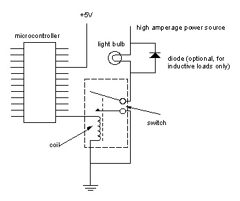
Digital output from a microcontroller is typically a low-amperage signal. For example, when a pin is set HIGH on the microcontroller (in Wiring/Arduino, it is digitalWrite(somePin, HIGH);), the voltage from that pin is usually +3.3V or +5V, with the...