
Games Timer Circuit With 4060 And 4017 IC

The game timer circuit utilizes the 4017 decade counter and the 4060 binary counter to manage timing and sequencing in a gaming application. The 4017 counter is designed to count from 0 to 10, providing a straightforward way to track game intervals or rounds. Upon receiving a reset signal, the 4017 counter is set back to its initial state, effectively restarting the game timer.
The 4060 counter, which operates as a frequency divider, is responsible for generating the clock pulses necessary for timing operations. It can be configured to produce a specific frequency based on external resistor and capacitor values connected to its timing pins. The output from the 4060 can be fed into the clock input of the 4017, ensuring that the counter increments at the desired intervals.
In the schematic, a reset mechanism is typically implemented using a push button switch connected to the reset pins of both counters. When the button is pressed, it sends a low signal to the reset pins, causing both the 4017 and 4060 counters to revert to their initial states. This feature is essential for restarting the timing sequence during gameplay.
Additional components, such as LEDs or display modules, may be integrated into the circuit to provide visual feedback on the current game state or timer status. The overall design should ensure that the power supply is stable, and decoupling capacitors may be included to filter out noise and ensure reliable operation of the counters.
In summary, this game timer circuit diagram showcases a practical application of digital counters to manage timing in gaming scenarios, with a focus on reset functionality and output management for user interaction.This is a games timer circuit diagram. When the games timer is RESET, two things must happen. The 4017 counter must go back to zero and the 4060 .. 🔗 External reference
Related Circuits
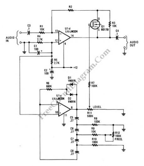
A tremolo circuit is a type of sound effect commonly utilized in guitar effect pedals. This effect is achieved by modulating the amplitude of an audio signal. The shape of the modulating signal can vary and may include square...
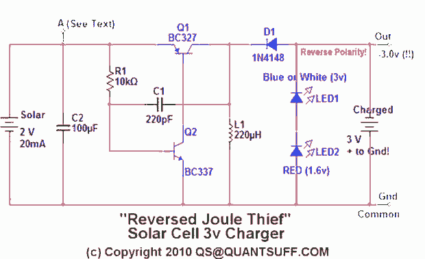
This design presents an innovative approach to the Joule Thief (JT) circuit typically utilized in garden lights. Instead of directly charging a 1.2V battery from the solar cell and converting the power to operate a 3-volt LED, this circuit...
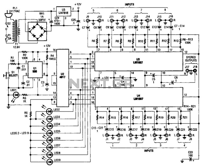
This source is selected by pressing a momentary-contact pushbutton switch (SI). Switch SI is connected to the trigger of a 555 oscillator/timer (U1) configured as a monostable multivibrator, which generates one short output pulse for each press of SI....
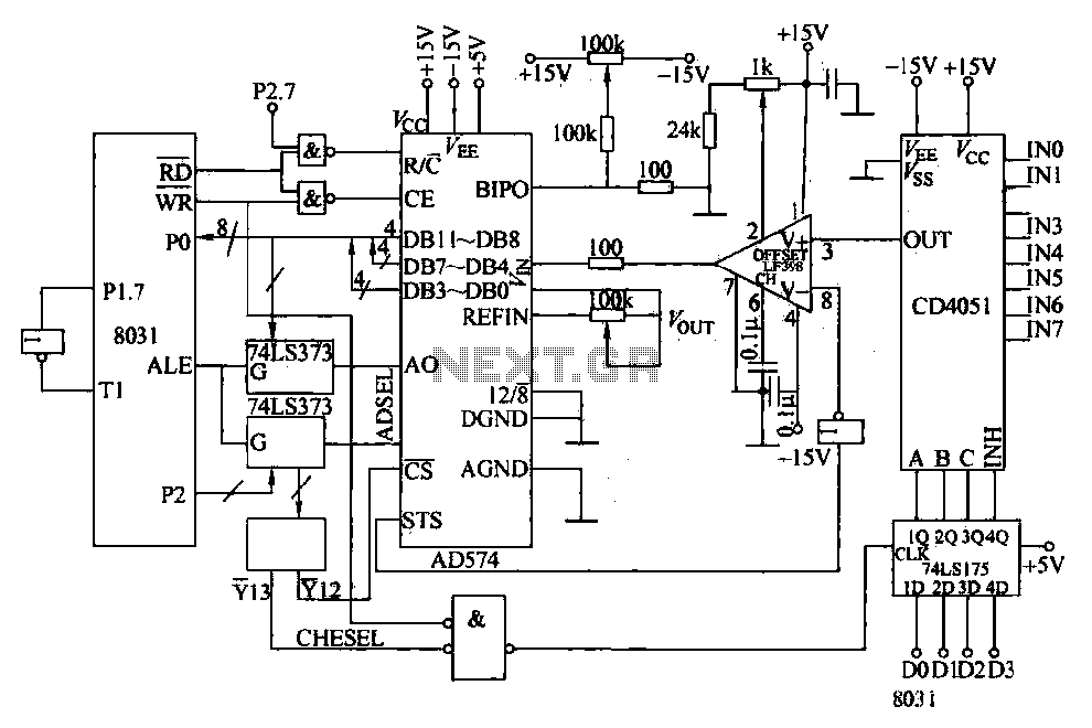
Converters and data sampling: A 12-bit A/D converter, AD574, is interfaced with an 8031 microcontroller circuit. Parameters are measured by a multi-way switch after a CD4051 strobe signal is sent to the sample/hold input device. The selection of the...
The 555 integrated circuit (IC) is configured in monostable mode of operation. In this mode, the output remains LOW (0V) when there is no trigger input. When a trigger is applied through pin 2, the output switches to HIGH...

A three-phase electric motor overcurrent protection circuit. This example circuit utilizes a transformer to monitor the current, ensuring that the currents in the three-phase motor do not exceed normal operating levels. When the current exceeds the set threshold, the...