
broadband rf power amplifier 18 30 mhz
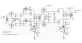
The push-pull configuration enhances attenuation of even harmonic frequencies, which is advantageous since the second harmonic is close to twice the fundamental frequency. Each output stage utilizes two separate transformers for each pair of MOSFETs, preventing power supply current from flowing into the output transformer, thereby avoiding saturation. The floating winding contributes to balance, harmonic attenuation, and stability.
The circuit incorporates a thermal stabilization and bias current regulation mechanism using a reliable LM723 integrated circuit, with transistors dedicated solely to PTT control. In the initial stage, a feedback circuit is implemented to optimize the gain-frequency response. Without this feedback, the low-frequency gain peaks excessively high at 50 dB at 3 MHz, dropping to 30 dB at 30 MHz. With the feedback circuit, the overall gain variation is maintained within +/-3 dB, which is an acceptable outcome. Attempts to apply similar feedback in the output stage were discarded due to poorer IMD performance.
MOSFET selection was conducted using a simplified method based on measuring drain-source resistance. A more precise approach would involve measuring the drain current at a specific gate voltage across all devices and selecting those that exhibit closer current values.
The RF Power Amplifier circuit is characterized by its efficient design for low-power applications, allowing for a straightforward implementation while ensuring stability and performance across the specified frequency range. The careful consideration of component selection, thermal management, and feedback optimization contributes to the overall effectiveness of this amplifier in QRP setups.Here`s RF Power Amplifier for QRP with low cost. This circuit is a broadband one from 1. 8 to 30 MHz, so it is "no-tune" and you need only to regulate the quiescent current bias multiturn trimmer of each Mosfets couple. This means also low efficiency (for a lower IMD it is even low as around 20-30%) together with good heat sink + blower system.
The push-pull configuration permits to get a better attenuation of even harmonic frequencies (a good benefit since the second is the closer 2x fundamental freq. ). The output stages have 2 separate transformers in each couples so the power supply current does not flow in to the output transformer to avoid saturation and the floating winding helps for balance for harmonic attenuation and stability.
We have emploied also in this low power unit the circuit found in higher power units to stabilise thermically and regulate the bias current around a trusted LM723 IC, the transistors are used only for PTT control. In the first stage Mosfet couple we have used a feedback circuit to optimize gain-frequency response.
Without it the low frequency gain is very high, too high: at 3 MHz 50 dB ! and a lower 30 dB at 30 MHz, but with this feedback circuit the overall gain variation is close to a +/-3 dB, a good result. We tried a similar feedback in the output couple but results where a poorer IMD performance so it has been omitted.
We selected Mosfets couples in a simplified way (while not so precise RF matching practice) measuring drain-source resistence: a better way could be to measure in a simple test circuit current drain at a given gate voltage applied for all devices and choose the ones that showed closer current values. 🔗 External reference
Related Circuits
As circuit power supply voltages decrease and green energy trends gain popularity, designers should re-evaluate circuits that continuously consume power to reduce overall system power consumption. One such circuit is the "normally-ON" circuit, which can now be redesigned with...
A Variable DC Power Supply is an essential tool for electronics hobbyists. This circuit, while not entirely new, is designed to be simple, reliable, robust, and short-proof. It offers variable voltage up to 24V and variable current limiting up...
Nowadays, it is no longer necessary to use discrete components to build oscillators. Instead, many manufacturers provide ready-made voltage-controlled oscillators. Modern electronic design has evolved significantly, eliminating the need for discrete components in the construction of oscillators. Voltage-controlled oscillators (VCOs)...
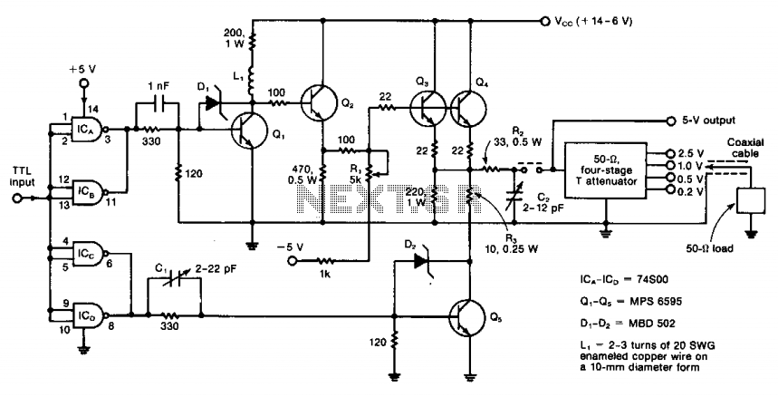
The circuit operates from DC to 50 MHz and is capable of delivering pulses as short as 10 ns. It is driven by a TTL signal through a 740S00 quad Schottky NAND gate, with input connections made via ICA...

The circuit depicted involves a main amplifier balanced by an electromagnetic pickup, line amplifiers, and a high tone control circuit. It includes components for an electromagnetic player, radio tuner, tape playback, and line input. The preamplifier utilizes an NE5532...
The SSY-1 is a compact pulsed Nd:YAG laser that was initially utilized as part of the laser rangefinder in the M1 Abrams tank. The laser head and PFN-1 pulse forming network, which includes a flashlamp capacitor, inductor, and diode,...