Power Supply for the SSY-1 YAG Laser
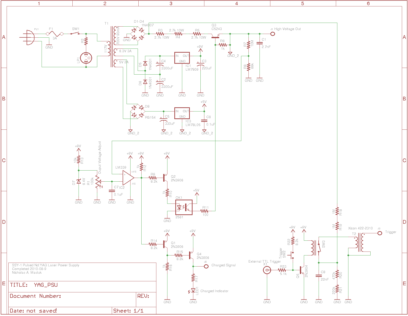
The SSY-1 is a compact pulsed Nd:YAG laser that was initially utilized as part of the laser rangefinder in the M1 Abrams tank. The laser head and PFN-1 pulse forming network, which includes a flashlamp capacitor, inductor, and diode, are readily available for under $250 as surplus items on platforms like eBay and Meredith Instruments. For further information about the laser, a valuable resource is Sam's Laser FAQ. Once the laser head and pulse forming network are acquired, the only remaining components needed for a fully functional laser are a power supply to charge the capacitor in the pulse forming network and a high-voltage trigger for the flashlamp. The power supply serves both of these functions. Aside from a few resistors and the trigger transformer, the entire assembly was constructed from scrap parts, allowing for the substitution of components with similar alternatives. The case and main power transformer originated from a pulsed argon laser, and the transformer was particularly suitable for this power supply, while the case was also compatible. Although the initial intention was to house all components except the laser head in a single enclosure, the case proved too small to accommodate the pulse forming network, resulting in its external placement alongside the laser head. The high-voltage regulator transistor Q3 was previously used as the horizontal output transistor in a monitor, selected for its sufficient voltage rating from a transistor collection. Any NPN transistor rated for 1200V or higher and capable of handling several hundred milliamps may be used. The capacitor within the pulse forming network operates at a voltage range of 700-900VDC, which is achieved by rectifying the 700V winding of transformer T1. Current limiting is managed by resistors R3-R5, while voltage regulation is handled by transistor Q3. The output voltage is divided using resistors R7 and R8, which is then compared to a reference voltage provided by a zener diode D7, adjustable via potentiometer R1. When the output voltage falls below the reference level, comparator IC2 activates the regulator transistor Q3 through transistor Q2 and optoisolator OK1. Due to the high potential at the emitter of Q3, an isolated 5V power supply is necessary to supply current to the base, with +5V referenced to GND_2 (indicated by downward pointing triangles). Potentiometer R1 can be adjusted to regulate the output voltage up to over 900V, with voltages exceeding this threshold posing a risk of damage to the laser. When the external capacitors reach the desired voltage, LED1 illuminates. To trigger the flashlamp, capacitor C8 discharges through the trigger transformer T2, generating a high-voltage pulse. C8 is charged via a resistive divider formed by resistors R18-R21, and activating relay SW3 allows the capacitor to discharge into the trigger transformer. The relay can be engaged by pressing a momentary toggle switch SW2 or by an external TTL trigger through the BNC connection X1.
The SSY-1 laser system is a complex assembly that requires careful consideration of each component's specifications and interactions to ensure optimal performance. The design integrates a high-voltage power supply with precise voltage regulation mechanisms, which are critical for the safe operation of the Nd:YAG laser. The use of surplus parts not only reduces costs but also emphasizes the importance of component compatibility and adaptability in electronic design.
The pulse forming network is a crucial element that must be configured to handle the high voltages involved in laser operation. The selection of the appropriate high-voltage regulator transistor is essential, as it must reliably manage the output voltage while maintaining stability under varying load conditions. The feedback loop created by the voltage divider and the comparator ensures that the output voltage remains within safe operational limits, preventing potential damage to the laser head.
The trigger mechanism for the flashlamp is another critical aspect of the design. The ability to generate a high-voltage pulse quickly and efficiently is vital for the laser's operation. The use of a relay for triggering provides flexibility, allowing for manual or automated operation depending on user requirements.
In summary, the SSY-1 laser system exemplifies the integration of various electronic components into a cohesive unit capable of high-performance operation. The design highlights the importance of voltage regulation, component selection, and trigger mechanisms in the successful implementation of high-voltage laser systems.The SSY-1 is a small pulsed Nd YAG laser originally used as part of the laser rangefinder in the M1 Abrams tank. The laser head and PFN-1 pulse forming network (flashlamp capacitor, inductor and diode) are readily available for under $250 as surplus on eBay and Meredith Instruments.
For more information on the laser, a useful source of informatio n is Sam`s Laser FAQ. With the laser head and pulse forming network in hand, all that is left to have a complete working laser is a power supply to charge the capacitor in the pulse forming network, and a high voltage trigger for the flashlamp. The power supply here fulfills these two roles. With the exception of a few resistors and the trigger transformer, I built this entirely from scrap parts I had, so none of the components are particularly special and may be substituted with a similar component.
The case and main power transformer were originally part of a pulsed argon laser, and the power transformer just happened to be ideal for this power supply, and the case worked nicely as well. I originally wanted to have everything except the laser head in one box, but this case was far to small for the pulse forming network to fit inside, so now it sits externally with the laser head.
The high voltage regulator transistor Q3 was originally the horizontal output transistor in a monitor, and I chose this transistor because it was literally the first one I picked out of my transistor bin with a high enough voltage rating. Any NPN transistor with a voltage rating at or above 1200V that can handle a few hundred milliamps should do.
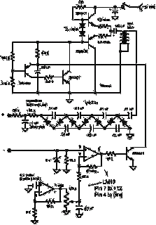
The capacitor in the pulse forming network requires between 700-900VDC. This voltage is provided by rectifying the 700V winding of T1. Current limiting is provided by resistors R3-R5, and the voltage is regulated by Q3. The output voltage is divided by resistors R7 and R8 and compared to a zener diode D7 reference voltage that is adjusted by potentiometer R1. When the output voltage is low with respect to the reference, comparator IC2 turns on the regulator transistor Q3 via transistor Q2 and optoisolator OK1.
Because the emitter of Q3 is at a high potential, an isolated 5V power supply is required to provide current to the base (note that in this schematic +5V is referenced to GND_2, where GND_2 is represented by downward pointing triangles). Potentiometer R1 may be adjusted to regulate the output voltage to any voltage up to over 900V (voltages above this may cause damage to the laser).
When the external capacitors charge to the desired voltage, LED1 will light. To trigger the flashlamp to fire, capacitor C8 is discharged through the trigger transformer T2 which generates a high voltage pulse. C8 is charged through the resistive divider formed by R18-R21, and activating relay SW3 allows the capacitor to discharge into the trigger transformer.
The relay may be activated either by pressing a momentary toggle switch SW2, or externally triggered via TTL on BNC connection X1. 🔗 External reference

