
Multifunctional Hi-Fi preamplifiers
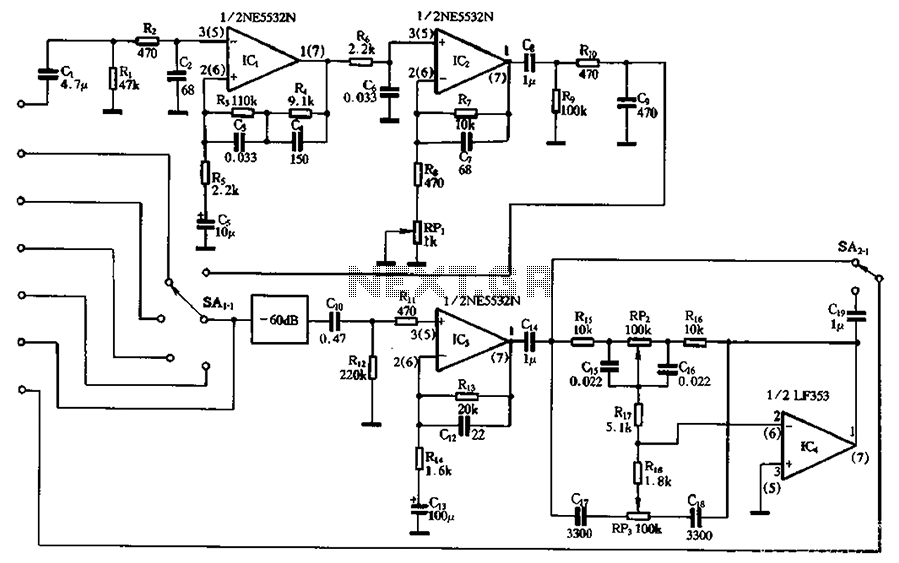
The circuit design integrates multiple functionalities essential for audio signal processing. The NE5532 operational amplifier serves as the core of the preamplifier stage, providing low noise and high fidelity, which is critical in preserving audio quality. The phono equalizer amplifier's feedback mechanism is a crucial aspect, as it ensures that the output closely adheres to the RIAA equalization curve, which is vital for vinyl playback systems. The use of negative feedback in the low-frequency range not only enhances the audio signal's clarity but also minimizes distortion, allowing for a more accurate representation of the original sound.
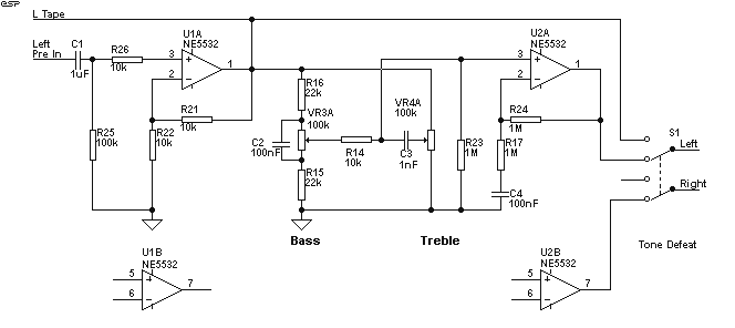
The tone control circuit, formed by IC4 and associated components, allows for user-friendly adjustments of the audio output, enabling listeners to tailor the sound to their preferences. The inclusion of a switch to bypass the tone control circuit indicates a design consideration for maintaining audio integrity when tone adjustments are not required.
Overall, the circuit is designed for high performance, with attention to component quality and layout to minimize interference and maintain signal integrity. The symmetrical power supply ensures stable performance, further enhancing the reliability of the audio processing capabilities. This comprehensive design approach caters to high-fidelity audio applications, making it suitable for various audio devices, including turntables, tuners, and tape players. Circuit shown in Figure 3 a child opening the main amplifier balanced by the electromagnetic pickup, line amplifiers and high tone control circuit consisting of roads and other parts for electromagnetic player, radio tuner, player, tape playback and line input as before preamplifier is o NE5532 integrated operational amplifier circuit assembly, having a high signal to noise ratio, low transient distortion, etc., it has a high technical performance art. Electromagnetic attenuation using a phono equalizer amplifier feedback equalization amplification clamor, because it has a high technical performance o like negative feedback phono equalizer amplifier by means of a large negative feedback loop to get the RIAA standards prescribed.
The depth of the negative feedback helps reduce harmonic distortion and improve signal to noise ratio, but sometimes increases transient distortion, high fidelity make the circuit is not guaranteed. Resistive and capacitive attenuation equalizer amplifier is a resistor-capacitor network in parallel with the signal path through the attenuation network of regulatory signals to comply with prescribed standards RIAA.
The disadvantage of this approach is balanced after the adoption of a balanced network, signal attenuation is large, and therefore need to increase the network after equalization amplifier stage, to make up for the loss of network signal attenuation gain. This circuit combines the characteristics of the two circuits, using an attenuated feedback phono equalizer amplifier.
In the low moon paragraph (20H ~ lkH) using negative feedback in a balanced manner, due to lower this frequency and the use of an appropriate amount of negative feedback, the electric path at low frequency distortion and signal to noise ratio has greatly improved. For 1kffi- 20kHz high-frequency band by R6.C6 composed by attenuating the attenuation network to eventually meet the standards o RIAA circuit decorated by the late Choi Ilcz make a total magnification so it reaches the desired output level of 35 ~ 40dB.
Line amplifier by the Ic3 and related components. It input signals, including players, tuners, phono, line input, as appropriate amplification to meet the post-amp input level required, and also the front, between the level reached after the output and input impedance reasonable match. The amount of amplification level is about 25dB. IC4, arsenic, RP3 and related components consisting of attenuated tone control circuit, high, bass control, if need sound tone control, a tone circuit I will cut through the switch carp rainbow, directly after the input signal level from the IC3 amplifier circuit.
This circuit should be of high quality components assembled, resistance should use metal film resistors, Class I accuracy. Use electrical capacitance polyol content. Power should use the symmetrical power supply.
Related Circuits
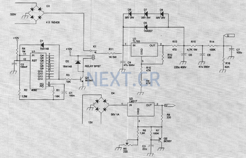
The amplifier feeding the final amplification stage operates with unstabilized voltage. The output stage, utilizing push-pull operation, exhibits significant rejection of the supply voltage. However, the earlier stages do not provide the same level of rejection, resulting in unwanted...
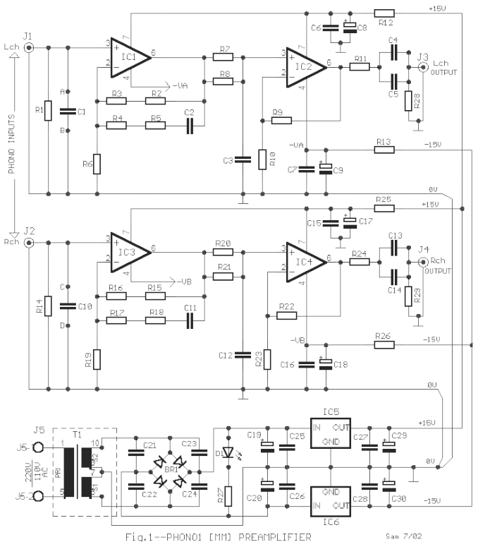
The circuit was designed according to the RIAA implementation of a Hi-Fi phono preamplifier for the purpose of reproducing audio from a moving magnet cartridge. The RIAA (Recording Industry Association of America) equalization curve is essential for the accurate playback...
Designing an audio amplifier from scratch using discrete components is an engaging task, as it enables users to create amplifiers that meet diverse requirements. Audio amplifiers can enhance low-level sounds from mobile devices, making them louder and more vibrant....
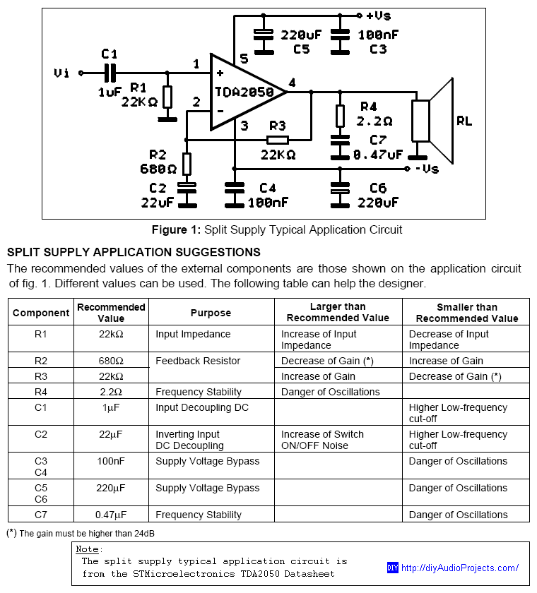
DIY TDA2050 Non-Inverting Chip Amplifier project constructed on a protoboard. The TDA2050 is a popular audio power amplifier integrated circuit designed for various audio applications. This non-inverting amplifier configuration is particularly valued for its simplicity and effectiveness in delivering high-quality...
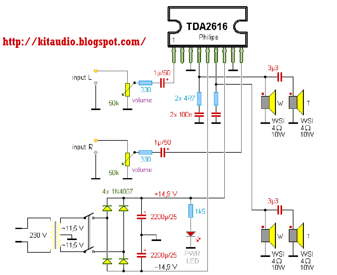
The TDA2616 is a hi-fi stereo amplifier designed for mains fed applications, such as stereo radio and TV. The circuit is optimally designed for symmetrical power supplies, but is also well-suited to asymmetrical power supply systems. An output power...
The preamp featured has optional tone and balance controls which may be omitted if desired. The input switching may be extended if needed to accommodate more signal sources. In this version, no RIAA (phono) input is provided. See the...
Warning: include(partials/cookie-banner.php): Failed to open stream: Permission denied in /var/www/html/nextgr/view-circuit.php on line 713
Warning: include(): Failed opening 'partials/cookie-banner.php' for inclusion (include_path='.:/usr/share/php') in /var/www/html/nextgr/view-circuit.php on line 713