
Brovin Kacher Tesla
The circuit described involves the generation and manipulation of RF frequency AC, which is characterized by its alternating nature where voltage oscillates between positive and negative values. The use of an oscilloscope is essential for visualizing the waveform, while conventional voltmeters may not accurately reflect the dynamic nature of the voltage due to their averaging characteristics. The interaction of the AC current with nearby magnetic fields can be observed through the behavior of a compass, which remains unaffected by the fast-changing current.
In this application, the wire surrounding the battery acts as a secondary winding of a transformer, with the battery's output current functioning as the primary source. The integration of a capacitor across the battery serves to attenuate RF currents, which can be beneficial in controlling the circuit's performance. The potential for high voltage spikes to feedback into the battery highlights the importance of considering capacitive coupling in circuit design.
The experiments conducted with microwave oven high-voltage capacitors demonstrate innovative approaches to enhancing circuit performance. The noted improvement when separating the capacitor from the battery indicates the significance of physical configuration in achieving desired electrical characteristics. The challenge of creating a spark gap emphasizes the need for careful component selection and circuit tuning.
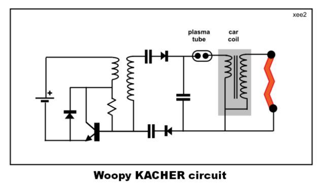
To optimize frequency response, the self-resonant frequency of the coil must be considered, and adjustments can be made through the addition of capacitors. The choice of transistors, such as the MJE13007 and IRF630, plays a crucial role in determining the circuit's operational frequency range and efficiency. Overall, this circuit exemplifies the intricate relationship between frequency, current flow, and component interaction in advanced electronic applications.The "cold electricity" is actually RF frequency AC. When you have sinusoidal AC the voltage is half the time positive and half the time negative. On a scope you can see this, but on a voltmete r the positive and negative parts cancel each other out. So the meter reads zero (because the meter can not respond fast enough to show the changing voltage). The current is also half of the time going one way and the other half going the other way which causes a DC amp meter to read zero since the needle can not go back and forth as fast as the current so it just stays put.
This will also cause a compass held near wire to not be effected by the AC current since again the needle can not go back and forth as fast as the current changes. The wire around the battery is the secondary of a transformer with the primary being the current flow in the battery.
Current is flowing out of the battery at RF frequency. Putting a capacitor across the battery will reduce this RF current flow in the battery. Note that in many circuits high voltage spikes are being fed back into the battery which can be capacitively coupled to a plate. As the frequency of the AC increases the current flows more and more along the surface of the conductor (including you).
At RF frequencies the current is only hundredths of an inch deep and not as deep as the nerves in your skin. That is why you do not feel a shock from RF current. However, if the current is strong enough it will burn your skin (called RF burns). I like this circuit allot and i am planning to make the 555 part variable so i can change frequency. But the antenna is also very nice to get things in resonance. If you look at the end of this video you see you can also get streamers from the antenna and circuit keeps working fine.
After looking at your induction video with wire around battery again, I do not think I was correct when I said it was acting like secondary of transformer. The current in the battery is not flowing in proper direction and there are not enough turns to get over 350 volts.
Rather, it seems to be just another way of making a capacitor plate. You certainly do come up with some very interesting circuits. Thanks again for sharing your results. You could check the capacitor coupling theory by replacing the wire around the battery with a capacitor (maybe 1 uF) connected to the negative or positive terminal of battery (whichever forms the outer case of the battery). so i used my second (not coil wrapped ) battery as power supply, and i connected one lead from a Micro wave owen HV cap (MOcap ) in place of the wrapping, with a connection to the negativ of the battery, and from the other lead, i connected a wire to the " captret" of the " cap avramenko- to car coil.
in a first time i placed the MOcap against (in contact ) the battery, but than i noticed that i can separate the cap from the battery with even better results. But further more i got even better results when i connect the neg of the battery to one of the MO cap and connect the CAPTRET of this cap to the other ( Avramenko MOcap to car coil )`s captret.
The cap still has its resistor inside and I manage to charge it quickly to more than 500 V. Nevertheless, it is almost impossible to make a spark jump to the other cap electrode/plate, even when the spark gap is set very narrow. The upper frequency limit is set by coil self resonant frequency. To lower frequency put capacitor in parallel with either coil. If transistor is not fast enough it can limit frequency also. MJE13007 should work up to several MHz. Thanks. Seems I resolved problem by placing irf630 between emitter and ground of mje13007 and driving it from oscillator type.
Because I`m not good in electronics it took me two days to construct circuit and probably will take another two to make a board in copper. I wonder if I can check the output waveform somehow with 🔗 External reference
Related Circuits
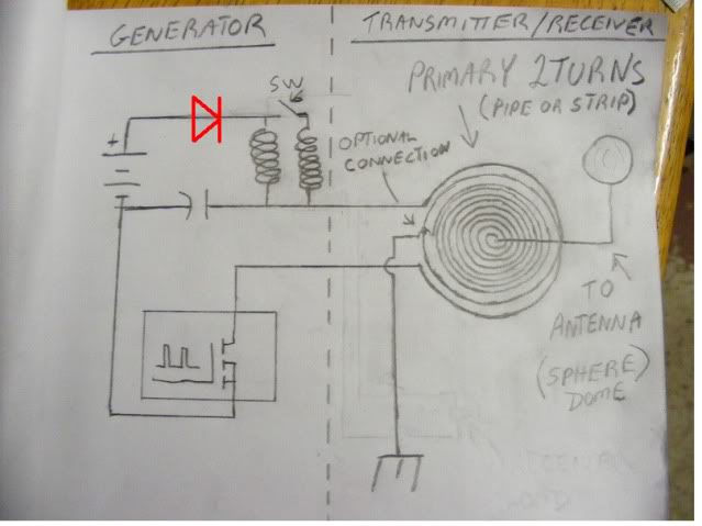
At approximately 50 kHz, a voltage exceeding 40 volts is observed at the receiver. LEDs illuminate without issues, although a 5mm LED was damaged. A capacitor connected to the AC was obstructing energy transfer. The primary negative was connected...

The Tesla Coil will utilize a high voltage (HV) power source that outputs 9 kV at approximately 30 mA. The construction of the Tesla coil includes six glass bottles, table salt, oil, and aluminum foil for the capacitors. The...
A Singing Tesla Coil is being developed for a 4-H electricity project, and the initial draft of the circuitry has been completed. The Singing Tesla Coil is an innovative device that produces high-voltage, high-frequency alternating current (AC) electricity, resulting in...
Every inexpensive energy-saving lamp contains a self-resonant voltage inverter designed for low-power operation, typically up to a few watts. It raises the question of why not scale up this concept and replace the resonance circuit used to generate the...
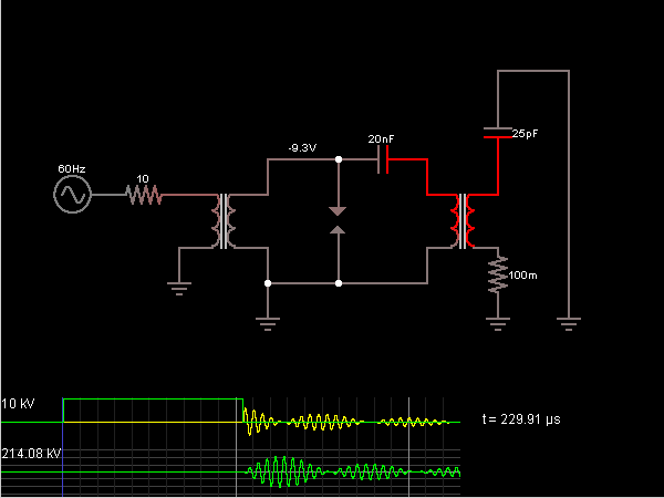
This is the Tesla Coil circuit diagram with a detailed explanation of its working principles. The electronic circuit simulator aids in designing the Tesla Coil circuit and simulating it online for better understanding. The Tesla Coil is a resonant transformer...

An inverter circuit is designed to power electroluminescent (EL) backlights and fluorescent tubes, producing an output of approximately 127 VAC. However, the objective is to achieve an output of 1 kV or more to generate at least 1 mm...