
Tesla coil circuit

The Tesla coil operates by transferring electrical energy through the primary coil to the secondary coil, where the energy is amplified. The high voltage power source energizes the primary coil, creating a magnetic field that induces a voltage in the secondary coil. The use of aluminum foil and glass bottles as capacitors enhances the coil's ability to store and discharge energy effectively.
The primary coil's copper tubing is designed to maximize the surface area and minimize resistance, allowing for efficient current flow. In contrast, the secondary coil, constructed from 24 AWG copper wire wound around PVC, is engineered to produce high-frequency oscillations. The discharge terminal serves as the point where the generated high voltage is released, creating spectacular electrical discharges.
During initial tests, an incandescent bulb demonstrated unusual behavior, with the filament projecting a plasma-like substance onto the glass. This phenomenon, although intriguing, ultimately led to the filament's burnout. The high-voltage environment posed risks to sensitive equipment; for instance, the camera used for documenting the experiments was unable to capture high-quality images due to the rapid discharge of electrical energy, resulting in poor image quality.
Subsequent to the experiments, the high voltage power source suffered damage, leading to the cessation of further tests. The design and construction of the Tesla coil illustrate the complexities and challenges involved in high-voltage experiments, highlighting the need for careful handling and protective measures when working with such equipment.The Tesla Coil I’ll be using will use a HV (High Voltage) power source that gives off 9 kV at around 30 mA. The rest of the Tesla coil will be made of 6 Glass bottles, Table salt, Oil, and Aluminum foil for the capacitors, the Primary coil will be made of around 10 feet of copper tubing, the secondary coil will be made of 1.5" PVC, 300 feet of 24 AWG copper wire, 1.5" PVC screw thing, 1.5" Metal floor flange, Spray on enamel, and the Discharge Terminal.
Interesting Note(s): 1. The Incandescent had an interesting effect during the Contact test. The filament in the center projected a Plasma-like Substance to the glass on the outside of the bulb, not even close to normal, functioning. This lasted for a few seconds; it then burnt out the filament. 2. The Camera I was using for the experiments was not able to be close enough to get high-quality pictures without being zapped by the Tesla Coil lighting, ruining the Camera.
The Photos taken did not show up well as it was (the lightning-like things were too fast to be captured. (All photos are taken off of Google Images) 3. After the experiments I had a little fun playing with it. And this resulted in the HV power source frying, resulting in the Tesla coil breaking. Further Tests have come to a standstill and will not be returning. 🔗 External reference
Related Circuits
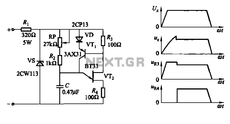
A conventional single junction transistor trigger circuit is limited to producing narrow pulses due to the rapid turn-off characteristics of the single-junction transistor. To address this limitation, a PNP transistor is added to the single-junction transistor trigger circuit, which...
The inductor is made by winding 8 turns of #24 insulated solid copper wire on a 5 mm screwdriver. I used a conductor from a piece of category 5 quad twisted pair, left over from wiring the house with...
The Pulse Demodulator, as illustrated in the accompanying image, consists of a CMOS Hex Inverter. This circuit is capable of performing envelope detection on amplitude pulses. The Pulse Demodulator utilizing a CMOS Hex Inverter is designed to extract the envelope...
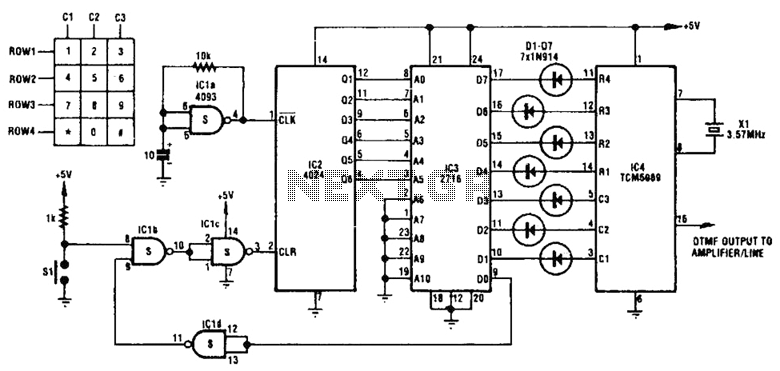
This circuit utilizes inexpensive, commonly available components to generate a precise dial tone for telephone applications. The Intel 82C54 timer-counter (U1) produces square wave signals at frequencies of 350 Hz and 440 Hz, which are subsequently filtered by resistors...
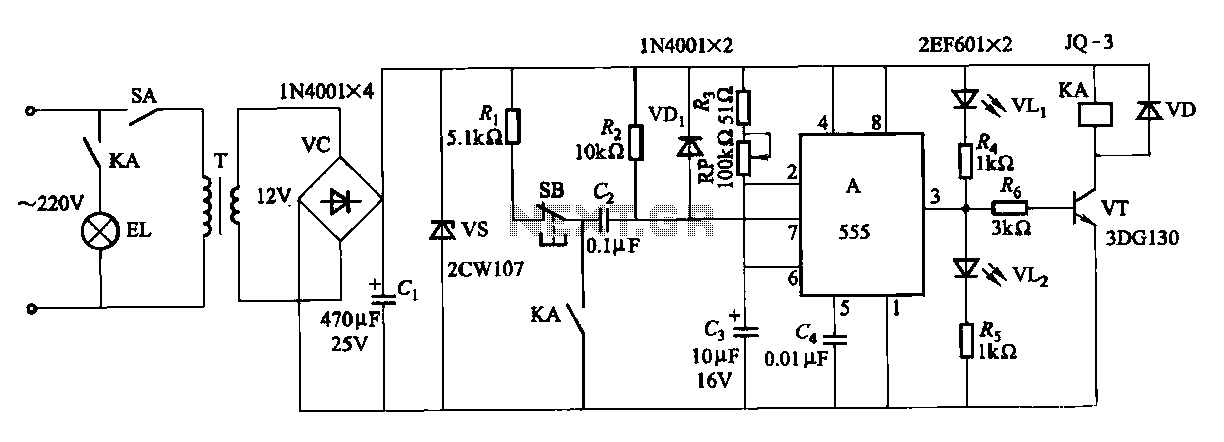
The second circuit for darkroom time exposure utilizes a 555 timer integrated circuit (IC A) for timing functions. A relay controlled by the circuit regulates the exposure light source. The exposure time can be adjusted using potentiometer RP, allowing...
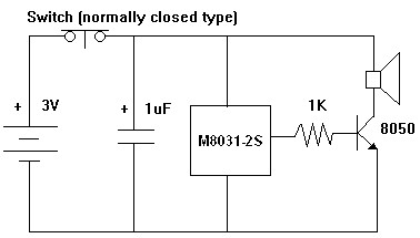
The M8031 circuit features an integrated RC oscillator and digital envelope circuits, which minimize the need for external components. It produces a sound that mimics a mechanical ding-dong. The M8031 operates with a low input voltage range of 1.3...