
Audio Controlled Switch Circuit

The audio-controlled switch circuit operates by detecting sound signals and converting them into a control signal that activates the connected devices. The core of the circuit comprises two 741 operational amplifiers configured in a non-inverting amplifier arrangement. These op-amps amplify the audio signal, enhancing the sensitivity of sound detection.
The amplified output from the op-amps is fed into a comparator stage, which determines whether the sound level exceeds a predefined threshold. This threshold is adjustable, allowing for customization based on the desired activation sensitivity. When the audio signal surpasses this threshold, the comparator output transitions from low to high.
This high output is then used to drive the base of the first 2N2222 transistor, which acts as a switch. The transistor is configured in common-emitter mode, providing significant current gain. When the transistor is turned on, it allows current to flow from the collector to the emitter, activating the second 2N2222 transistor, which can drive the hcxFET.
The hcxFET serves as an electronic switch that can handle higher currents and voltages, making it suitable for controlling larger devices such as tape recorders or transmitters. The entire circuit is powered by a suitable DC power supply, with bypass capacitors included to filter out any noise and stabilize the voltage levels.
Additional support components, such as resistors and capacitors, are utilized for biasing the transistors, setting the gain of the op-amps, and filtering the audio signal. Proper selection of these components is crucial to ensure the circuit's performance and reliability in various audio environments. Overall, this audio-controlled switch provides a versatile solution for sound-activated applications, combining simplicity with effective control capabilities. This audio-controlled switch combines a pair of 741 op amps, two 2N2222 general-purpose transistors, a hcxFET, and a few support components to a circuit that can be used to turn on a tape recorder, a transmitter, or just about anything that uses sound.
Related Circuits
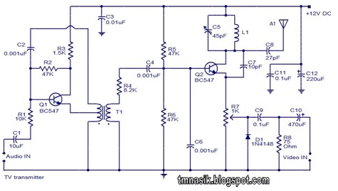
The TV transmitter circuit described utilizes UK standard 1 FM modulation for audio and PAL modulation for video. The audio signal intended for modulation is first amplified using transistor Q1 and its associated components. Transistor Q2 serves dual purposes:...
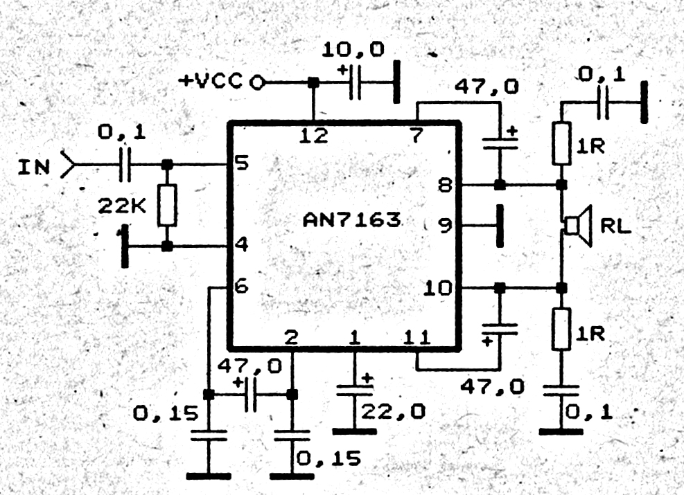
This 5.1 surround amplifier circuit schematic utilizes the IC AN7168 as the primary component. The circuit requires a minimum voltage of 12V and a maximum voltage of 24V, with a recommendation of 12V due to the voltage ratings of...

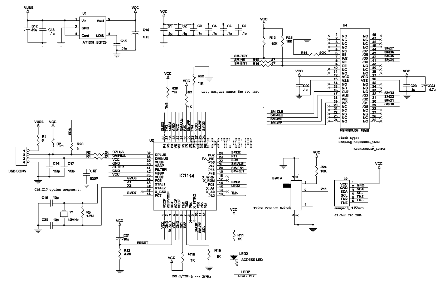
The composite pipe circuit limits the bulb cold current of the circuit. When the input signal is weak, a composite pipe circuit protection circuit is utilized, as illustrated in Figure 1. The composite pipe circuit functions as a protective mechanism...
Crystal 80mW FM transmitter circuit diagram of the production The Crystal 80mW FM transmitter circuit is designed to generate frequency modulated (FM) signals suitable for short-range audio transmission. This circuit primarily consists of a crystal oscillator, which serves as...
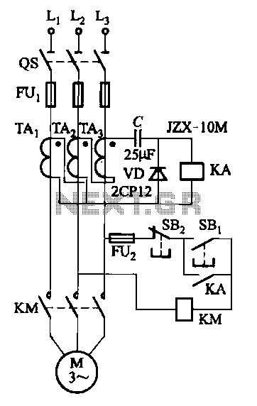
Figure 4-27 (b) line demonstrates a configuration that enhances the output current waveform DC voltage compared to the line in Figure 4-27 (a). This configuration can be utilized for motors with larger capacities. The circuit illustrated in Figure 4-27 (b)...
Infrared remote controls are using a 32-56 kHz modulated square wave for communication. These circuits are used to transmit a 1-4 kHz digital signal (OOK modulation) through infra light (this is the maximum attainable speed, 1000-4000 bits per sec)....