
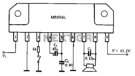
BTL amplifier circuit composed by M51516L IC
The BTL amplifier configuration is designed to drive a load without requiring a center tap on the output transformer, thus maximizing efficiency and power delivery. In this setup, each amplifier drives one side of the speaker load, effectively doubling the output voltage across the load compared to a single-ended configuration.
The circuit's power supply voltage of 13.2V is critical for achieving the specified output power of 12W. The choice of a 4-ohm speaker load is optimal for this application, as it allows the amplifier to deliver higher current, resulting in increased power output. The design should include appropriate filtering capacitors to smooth out the power supply voltage and decoupling capacitors near the amplifier ICs to reduce noise and enhance performance.
The integration of components such as resistors, capacitors, and feedback loops within the circuit is essential for stability and sound quality. The feedback mechanism ensures that the amplifier maintains linearity and minimizes distortion, which is crucial for high-fidelity audio applications.
Thermal management should also be considered in the design, as the amplifier will generate heat during operation. Adequate heatsinking and ventilation should be provided to maintain optimal operating temperatures and prevent thermal shutdown.
In conclusion, this BTL amplifier circuit is a compact and efficient solution for driving low-impedance speakers, making it suitable for various audio applications, including home theater systems and portable audio devices.Figure 1-44 is dedicated BTL amplifier circuit, containing two single amplifier, and has integrated the relevant elements in the circuit, so the connection is very simple. The circuit at 13, 2V power supply voltage, output 12W load speaker on 4n maximum power.
Related Circuits
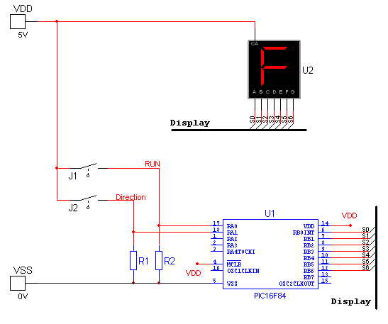
National Instruments Multisim now features microcontroller unit co-simulation capabilities, enabling the inclusion of a microcontroller, programmed in assembly or C code, within SPICE-modeled circuits. The MCU functionality in Multisim allows students, educators, and professional users to program MCUs in...
A 2 x 18W Hi-Fi Stereo Power Amplifier is designed using two TDA2030 integrated circuits (ICs). This amplifier features excellent input sensitivity, low distortion levels, stable operation, and comprehensive protection against overloads and output short circuits. It can serve...
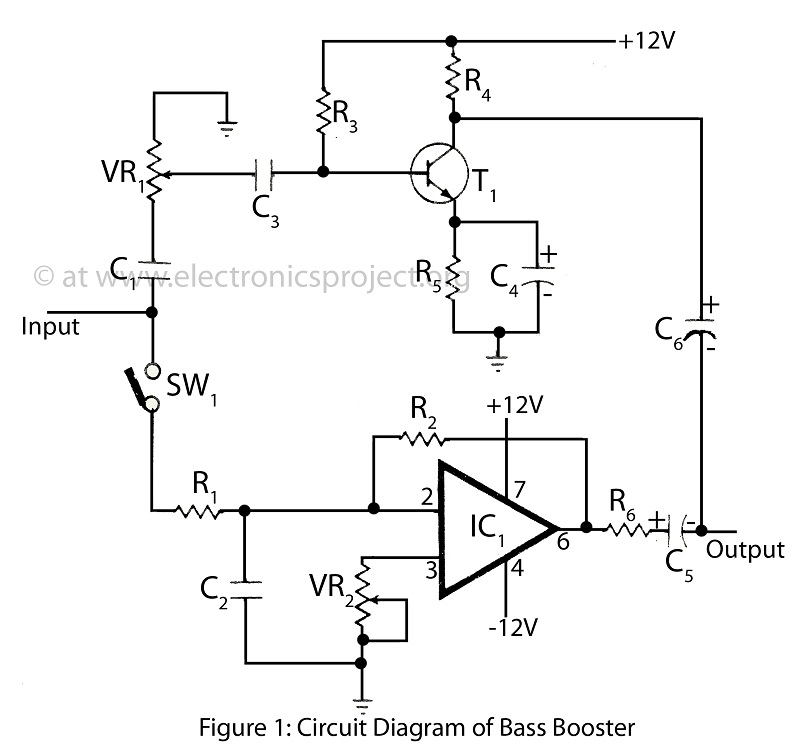
The bass booster featured on this website enhances the beat frequency while maintaining the integrity of the high-frequency response. The circuit diagram for the bass booster, along with various radio circuits, is also provided. The bass booster circuit operates by...
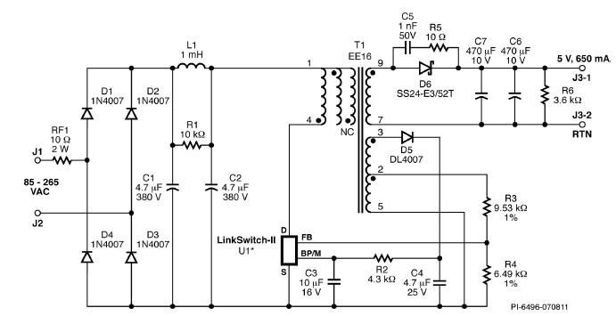
A simple 3.25W constant voltage/constant current (CV/CC) charger can be designed using the LinKSwitch family IC manufactured by Power Integrations. This electronic circuit project is intended to provide a 5-volt output with a maximum current of 650mA. The 3.25W...
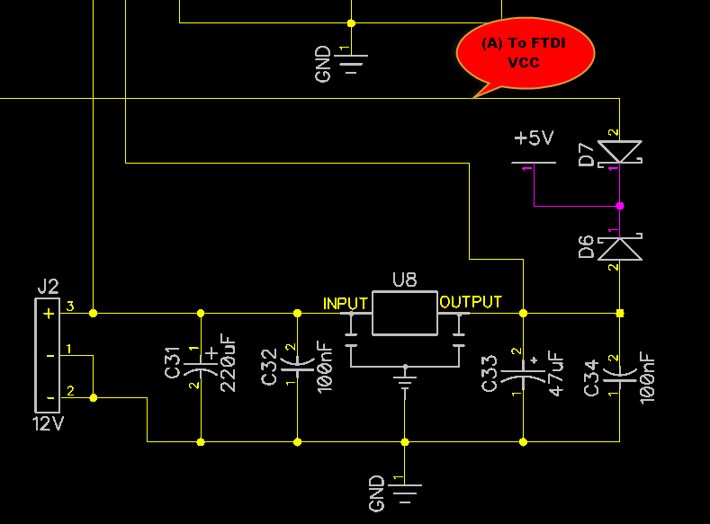
When only the voltage regulator (VR) supplies power to the circuit, the microcontroller unit (MCU) will receive power from the +5V bus, while the FTDI chip will only receive VCCIO. At the midpoint of the voltage divider formed by...
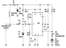
The sections available in this datasheet cover general design considerations for the 555 timer, frequently asked application questions (FAQ), design formulas, and examples of innovative applications. Examples of applications include a Missing Pulse Detector, Pulse Width Modulation (PWM), Tone...
Warning: include(partials/cookie-banner.php): Failed to open stream: Permission denied in /var/www/html/nextgr/view-circuit.php on line 713
Warning: include(): Failed opening 'partials/cookie-banner.php' for inclusion (include_path='.:/usr/share/php') in /var/www/html/nextgr/view-circuit.php on line 713