
Would this USB detection circuit work as expected
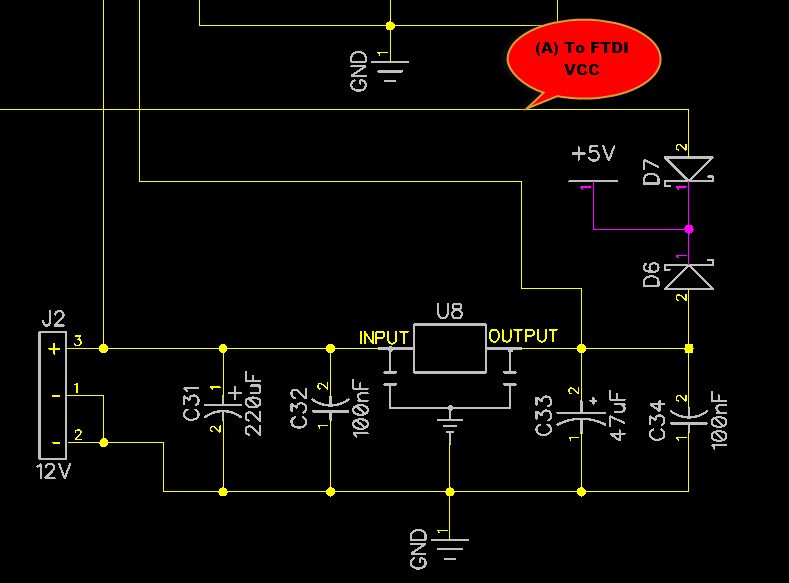
In this circuit configuration, the voltage regulator (VR) serves as the primary power source, providing a stable +5V supply to the microcontroller unit (MCU). The FTDI chip, which is commonly used for USB to serial communication, requires both a power supply (VCC) and an I/O voltage (VCCIO) to operate correctly. In this scenario, the MCU is powered from the +5V bus, ensuring it has the necessary voltage for its operation.
The FTDI chip, however, is only connected to VCCIO, which is typically used to set the voltage level for the I/O pins of the chip. This setup raises concerns about the functionality of the FTDI chip since it may not receive the required power supply (VCC) to operate properly. The voltage divider formed by resistors R10 and R11 is intended to create a reference voltage, but if the midpoint voltage is 0V, it indicates that the divider is not functioning as expected, potentially leading to an inability for the MCU to detect the USB connection.
The primary concern is whether supplying only VCCIO to the FTDI chip could result in damage or unpredictable behavior. Many digital components, including the FTDI chip, require a proper power supply to function correctly. Operating the chip without VCC may lead to undefined states, which could cause erratic behavior or even permanent damage to the device. It is crucial to ensure that the FTDI chip is provided with the appropriate power supply alongside the I/O voltage to guarantee reliable operation and prevent any adverse effects on the circuit.
In conclusion, it is advisable to revise the circuit design to include a stable VCC supply for the FTDI chip in addition to VCCIO to ensure proper functionality and avoid potential damage.When ONLY VR will supply power to circuit, then MCU again will get power from +5V bus, but FTDI will ONLY get VCCIO. On middle of voltage divider R10/R11 I expect there will be 0 and MCU will not detect USB connection on (B).
The question is - would it work the way I described or I missed something My concern is it ok to hook up only VCCIO to FTDI Would it damage or lead to unknown behavior 🔗 External reference
Related Circuits
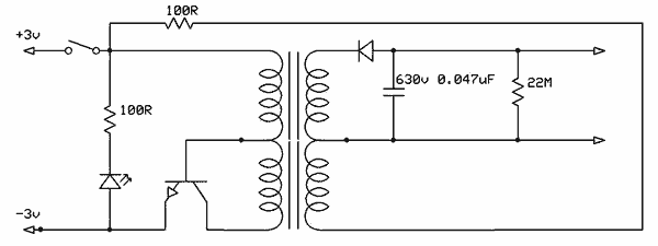
Free energy motors and generators are available for purchase, featuring plans for overunity devices. These devices resemble oscillators used in Joule thief circuits, although there may be some errors present in the designs. However, the concept remains clear. Free energy...

There are important considerations when using additional memory, but it is certainly feasible. The MP3 player project utilizes 32 megabytes of memory. However, using more memory necessitates careful planning. The key factor is that the 8051 processor has a...
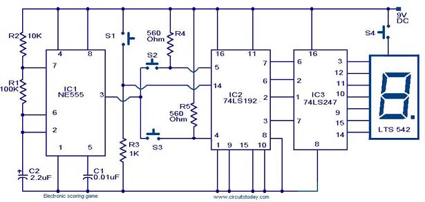
A scoring game circuit is explained with a circuit diagram and circuit parts. The scoring game circuit is designed to track and display scores in a gaming environment. The primary components of this circuit typically include a microcontroller, a score...
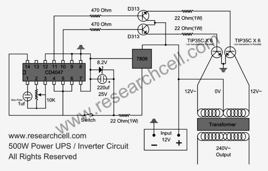
This circuit diagram features a single variable resistor utilized to adjust the frequency of a 240V AC output current. It is advisable to use a frequency meter to modify the frequency from 50Hz to 60Hz according to specific requirements....

The crystal equivalent RLC circuit is illustrated. The RLC circuit can operate in either a series resonant or parallel resonant configuration. The crystal equivalent RLC circuit is a fundamental electronic circuit that models the behavior of a crystal oscillator. This...
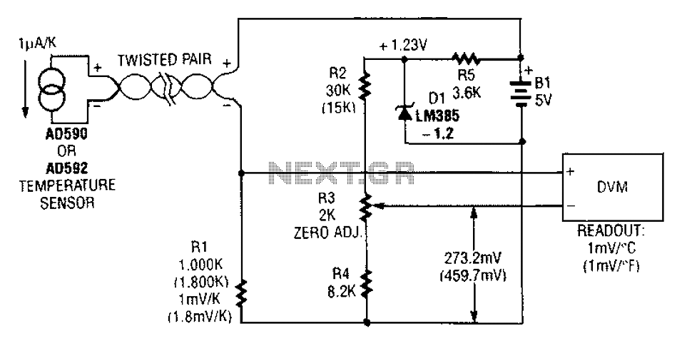
An AD590 or AD592 can be utilized in a transmission line for temperature data transmission. The circuit generates a value of 1 mV per degree Fahrenheit. The AD590 and AD592 are precision temperature sensors that output a voltage proportional to...