
Buck Boost Voltage Converter

The LTC 3440 buck/boost voltage converter is designed for applications requiring flexible voltage regulation from a battery source. It is particularly advantageous in portable devices where battery voltage can fluctuate significantly over its discharge cycle. The ability to switch seamlessly between buck and boost modes ensures that the circuit remains operational across a wide range of input voltages.
The MOSFET configuration within the IC is crucial for maintaining efficiency and performance. In boost mode, the continuous operation of switch A allows for the accumulation of energy in the inductor, which is then released to the output when switches C and D alternate. This method minimizes energy loss and maximizes the output voltage. Conversely, in buck mode, the consistent closure of switch D ensures that the output voltage can be regulated down effectively.
The choice of inductor, such as the DT1608C-103, is vital for maintaining a compact design while ensuring adequate performance. The high switching frequency of 1.2 MHz allows for smaller passive components, which is essential in space-constrained applications.
The implementation of soft-start functionality via an RC network is beneficial in preventing inrush current during startup, which can protect sensitive components downstream. The flexibility offered by the MODE pin allows designers to optimize for power efficiency based on the specific operational conditions of the application.
Overall, the LTC 3440 provides a robust solution for maintaining stable voltage levels in battery-powered circuits, enhancing the performance and longevity of electronic devices.Sometimes it is desired to power a circuit from a battery where the required supply voltage lies within the discharge curve of the battery. If the battery is new, the circuit receives a higher voltage than required, whereas if the battery is towards the end of its life, the voltage will not be high enough.
This is where the new LTC 3440 buck/boost voltage converter from Linear Technology ( can help. The switching regulator in Figure 1 converts an input voltage in the range +2. 7 V to +4. 5 V into an output voltage in the range +2. 5 V to +5. 5 V using one tiny coil. The level of the output voltage is set by the voltage divider formed by R2 and R3. The device switches as necessary between step-up (or boost`) operation when Vin is less than Vout, and step-down (or buck`) operation when Vin is greater than Vout. The maximum available output current is 600mA. The IC contains four MOSFET switches (Figure 2) which can connect the input side of coil L1 either to Vin or to ground, and the output side of L1 either to the output voltage or to ground.
In step-up operation switch A is permanently on and switch B permanently off. Switches C and D close alternately, storing energy from the input in the inductor and then releasing it into the output to create an output voltage higher than the input voltage. In step-down operation switch D is permanently closed and switch C permanently open. Switches A and B close alternately and so create a lower voltage at Vout in proportion to the mark-space ratio of the switch ing signal.
L1, together with the output capacitor, form a low-pass filter. If the input and output voltages are approximately the same, the IC switches into a pulse-width modulation mode using all four switches. Resistor R1 sets the switching frequency of the IC, which with the given value is around 1. 2 MHz. This allows coil L1 to be very small. A suitable type is the DT1608C-103 from Coilcraft ( The IC can be shut down using the SHDN/SS input. A soft start` function can also be implemented by applying a slowly-rising voltage to this pin using an RC network.
The MODE pin allows the selection of fixed-frequency operation (MODE connected to ground) or burst mode operation (MODE=Vin). The latter offers higher efficiency (of between 70% and 80%) at currents below 10 mA. At currents of around 100 mA the efficiency rises to over 90 %. A further increase in efficiency can be obtained by fitting the two Schottky diodes shown dotted in the circuit diagram.
These operate during the brief period when both active switches are open (break-before-make operation). 🔗 External reference
Related Circuits
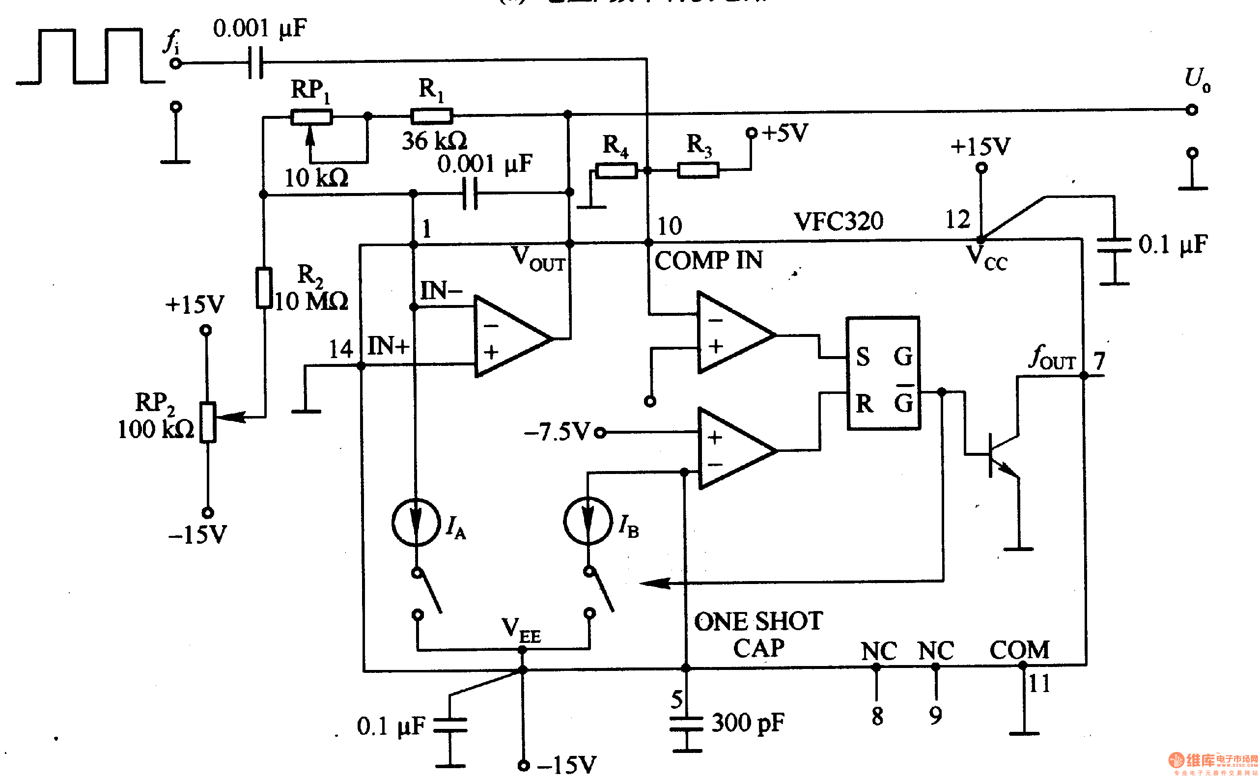
Figure 1-22 (a) illustrates a circuit that converts an input voltage of 0 to +10V (Ui) into a pulse with an output frequency ranging from 0 to 100kHz. In this configuration, pin 7 of the VFC320 is connected to...
As the demand for VRM output current increases, the components and parts of the SR-Buck converter can no longer meet the requirements for the new generation microprocessors needing 100 A. Additionally, creating filtering inductance for high currents is quite...
A digital camera has been purchased that is capable of capturing both images and videos. However, it has been reported that the camera has limitations related to battery life, which affects its operational duration. The digital camera operates using a...
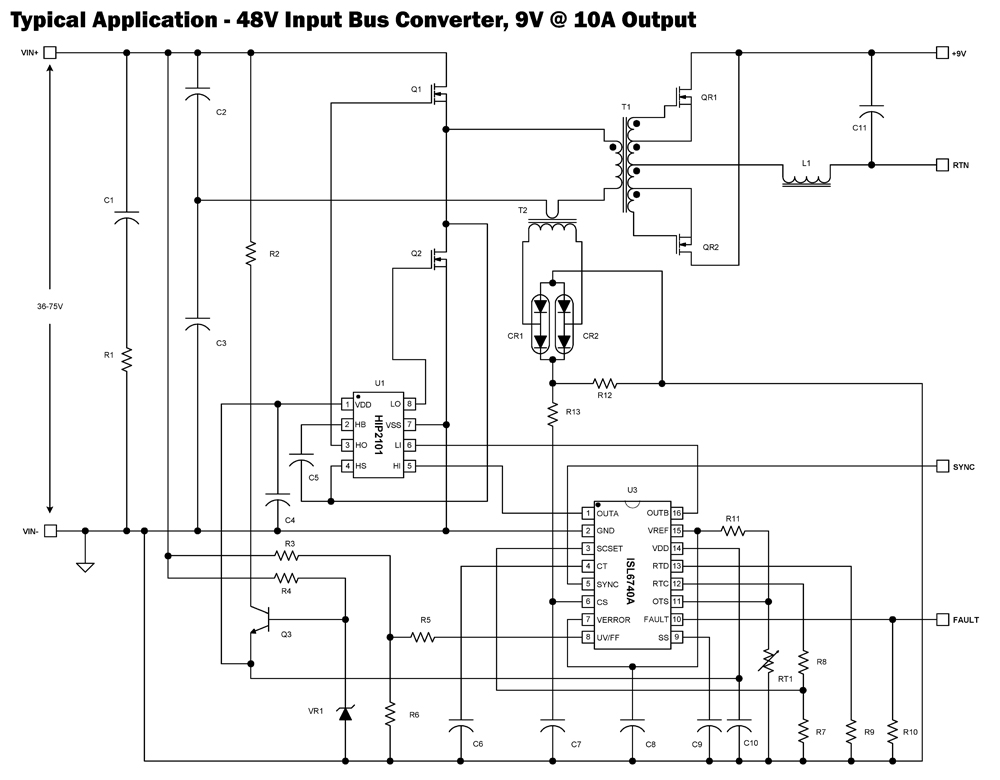
The ISL6740A is an enhanced PWM controller that incorporates built-in voltage feed forward functionality. It is pin and feature compatible with the ISL6740 double-ended pulse width modulation (PWM) voltage-mode controller, facilitating straightforward drop-in replacement in existing designs. Voltage feed...

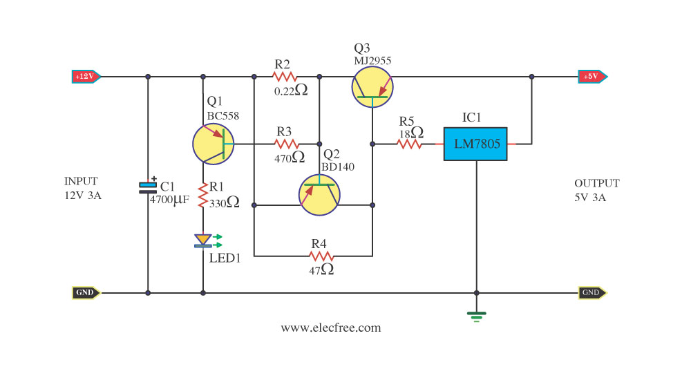
Voltage variations and power cuts adversely affect various equipment such as TVs, VCRs, music systems, and refrigerators. This simple circuit will protect costly equipment from high and low voltages and voltage surges when power resumes. It also produces a...
The designer is looking for a solution with higher efficiency and lower power consumption in order to minimize unnecessary energy loss. The approach involves using syntony inductance to harmonize the capacitive LLC syntony converter, employing zero voltage switching (ZVS)...
Warning: include(partials/cookie-banner.php): Failed to open stream: Permission denied in /var/www/html/nextgr/view-circuit.php on line 713
Warning: include(): Failed opening 'partials/cookie-banner.php' for inclusion (include_path='.:/usr/share/php') in /var/www/html/nextgr/view-circuit.php on line 713