
high and low voltage cut out with delay and music circuit diagram

The circuit described serves as a protective measure for sensitive electronic equipment against voltage fluctuations and interruptions in power supply. It utilizes zener diodes D4 and D5 to monitor voltage levels, ensuring that both high and low voltage conditions trigger appropriate responses. The use of transistors T1 and T2 facilitates the control of relay RL1, which disconnects the load during unsafe voltage conditions.
The Timer IC 555, configured in monostable mode, plays a crucial role in providing a time delay after power restoration, allowing the system to stabilize before reconnecting the load. The output from the Timer IC triggers a melody generator, IC UM66, through transistor T3, adding a functional feature to the circuit that signals the restoration of power.
The adjustment of presets VR1 and VR2 is essential for calibrating the circuit to the specific voltage thresholds that will trigger the relays. This calibration ensures that the equipment remains protected under varying conditions. The use of a manually adjustable auto-transformer allows for precise setting of these thresholds, enhancing the versatility of the circuit in different electrical environments.
Overall, this circuit design effectively combines protective measures with user-friendly features, ensuring the longevity and safety of valuable electronic devices.Voltage variations and power cuts adversely affect various equip- ment such as TVs, VCRs, music systems and refrigerators. This simple circuit will protect the costly equipment from high as well as low voltages and the voltage surges (when power resumes).
It also gives a melodious tune when mains power resumes. When mains voltage is normal, the DC voltage at the cathode of zener diode D4 is less then 5. 6V. As a result transistor T1 is in off state. The DC voltage at the cathode of zener diode D5 is greater than 5. 6V and as a result transistor T2 is in on state. Consequently, relay RL1 gets energised, which is indicated by lighting up of green LED. Under high mains voltage condition, transistor T1 switches to on state because the voltage at cathode of zener diode D4 becomes greater than 5. 6V. Consequently, transistor T2 switches to off state, making the relay to de-energise Under low mains voltage condition, transistor T1 switches to off state and as a result transistor T2 also switches to off state, making the relay to de-energise.
Timer IC 555 in the circuit is configured to operate in a monostable mode. The pulse width is about 10 seconds with the timing component values used in the circuit. When the power resumes after a break, pin 2 of IC 555 goes low briefly and this triggers it. Its output makes music IC UM66 to operate through transistor T3. Simultaneously, transistor T1 also gets forward biased as the monostable IC1 output is connected to its base via diode D8 and resistor R7. As a result, transistor T1 conducts and biases transistor T2 to cut off. Thus relay RL1 remains de-energised for the duration of mono pulse and the load is protected against the voltage surges.
To adjust presets VR1 and VR2, you may use a manually variable auto-transformer. Set the output of auto-transformer to 270V AC and connect it to the primary of transformer X1. Adjust preset VR1 such that relay RL1 just de-energises. Next set the output of auto-transformer to 170V AC. Now adjust preset VR2 such that relay RL1 again de-energises. Volume control VR3 may be adjusted for the desired output volume of the tune generated by IC UM66 Disclaimer: All the information present on this site are for personal use only. No commercial use is permitted without the prior permission from authors of this website. All content on this site is provided as is and without any guarantee on any kind, implied or otherwise.
We cannot be held responsible for any errors, omissions, or damages arising out of use of information available on this web site. The content in this site may contain COPYRIGHTED information and should not be reproduced in any way without prior permission from the authors.
🔗 External reference
Related Circuits
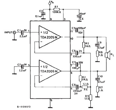
TDA2005 car audio amplifier circuit diagram electronic project using few external electronic parts The TDA2005 is a robust integrated circuit designed for audio amplification in automotive applications. This circuit diagram outlines a project for a car audio amplifier that utilizes...

This circuit was first introduced by Signetics Corporation as the SE555/NE555 around 1971. Pin connections and functions are as follows: Pin 1 (Ground) is the most negative supply potential of the device, typically connected to circuit common when powered...
This webpage details a highly efficient LED dimmer, which can also be referred to as a dimmable LED flashlight or a switching current source. It is an economical, single-integrated circuit (IC) solution that utilizes widely available components and is...
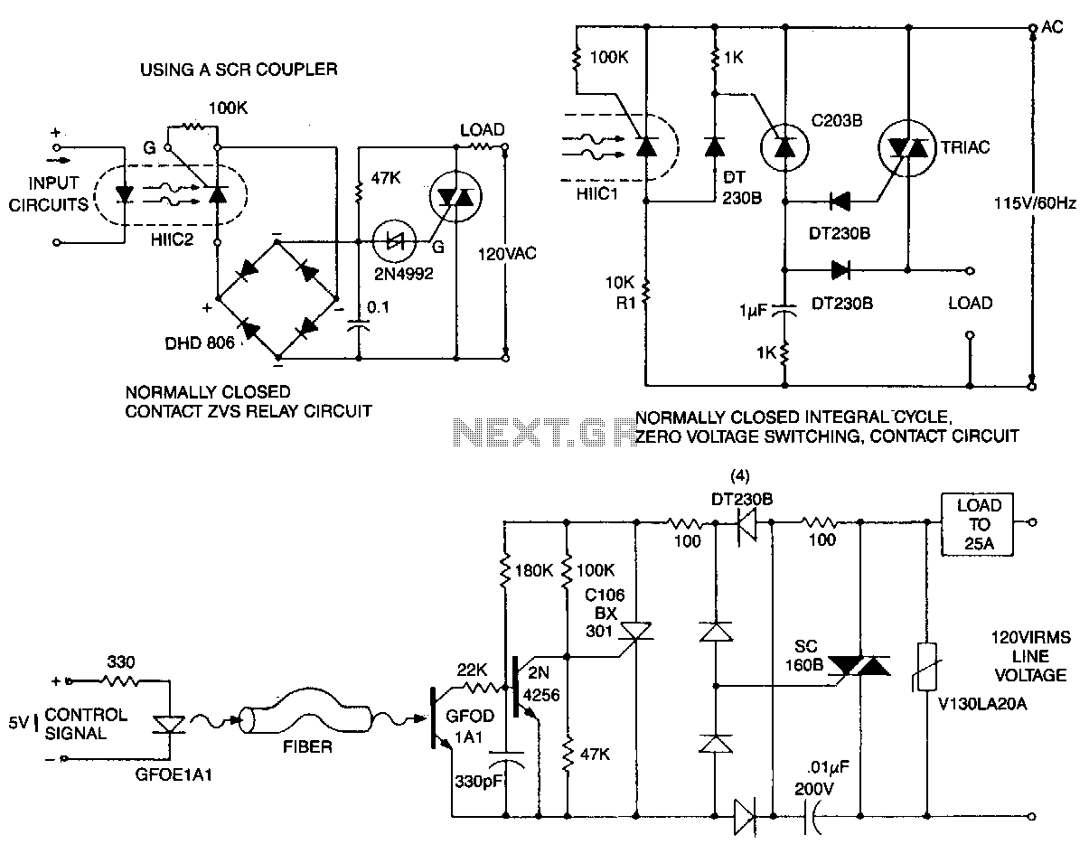
This circuit is effective for lamp and heater loads. Some circuits driving reactive loads require integral cycling and zero-voltage switching when an identical number of positive and negative half-cycles of voltage are applied to the load during a power...
Here is a link to the ExpressPCB layout for this compressor. If you are not familiar with ExpressPCB, look it up. They provide a layout tool that is very easy to use, and you can have boards manufactured for...
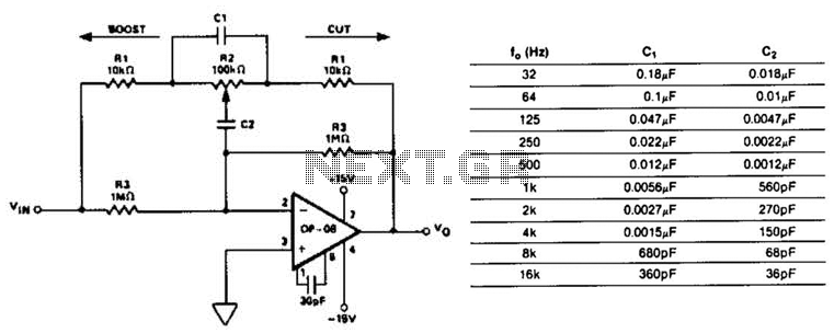
This circuit represents a section of an octave equalizer utilized in audio systems. The table outlines the values of C1 and C2 required to achieve specific center frequencies. This circuit can provide a boost or cut of 12 dB,...