
Buffer amplifier
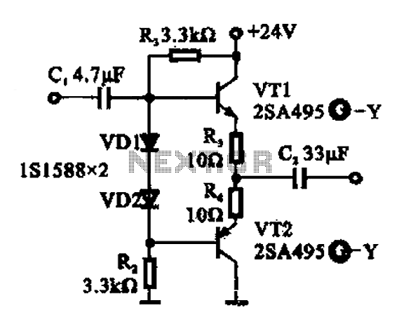
The buffer amplifier described functions primarily as an impedance matching device, allowing signals from high impedance sources to drive lower impedance loads without signal degradation. The configuration of the amplifier as an emitter follower ensures that the output voltage closely follows the input voltage while providing a significant increase in current drive capability.
In this circuit, the transistor VT1 acts as the main amplifying element. The high input impedance is achieved through the use of a resistor divider network that biases the base of VT1, allowing minimal loading on the input signal source. The inclusion of the two forward-biased diodes serves to stabilize the base voltage against fluctuations, enhancing the performance of the amplifier under varying conditions.
The complementary push-pull arrangement typically involves a second transistor, which can be configured to handle the negative half of the signal cycle, thereby improving linearity and reducing distortion. This configuration allows the circuit to efficiently drive loads while maintaining signal integrity.
The output stage of the buffer amplifier, characterized by its dual emitter output, results in low output impedance. This is advantageous for driving capacitive loads or long cable runs, as it minimizes signal loss and ensures that the load receives a faithful representation of the input signal. The overall design is particularly suited for applications in audio amplification, sensor interfacing, and other scenarios where signal fidelity and impedance matching are critical. Buffer amplifier Shown in use as a transistor emitter follower buffer amplifier for applications that require high input impedance of the amplifier. Complementary push-pull cir cuit the circuit configuration, the signal input from the base of VT1, two transistor base bias resistor divider type, the base of the transistor both indirect two forward biased diodes, to maintain the base voltage static stability, since the circuit dual emitter output circuit, because the output impedance and low output has strong ability.
Related Circuits
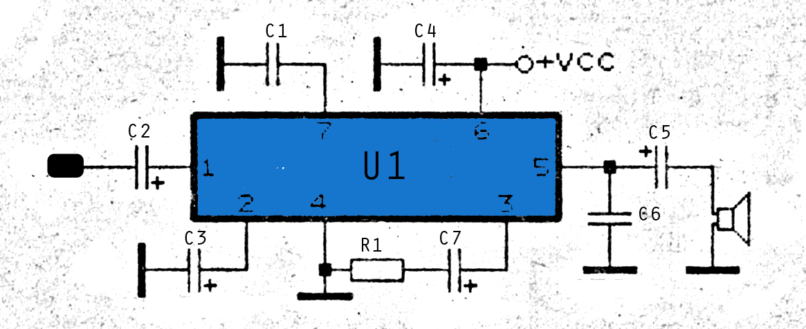
The integrated circuit LM386 is a low-power audio frequency amplifier that requires a low-level power supply, typically batteries. It is available in an 8-pin mini-DIP package. The IC is designed to provide a voltage amplification of 20 without the...
A friend is interested in building a hi-fi power amplifier, specifically a Class AB model due to its quality sound, particularly in bass response and distinct clarity. This circuit is designed as a hi-fi OCL (Output Capacitor-Less) power amplifier...
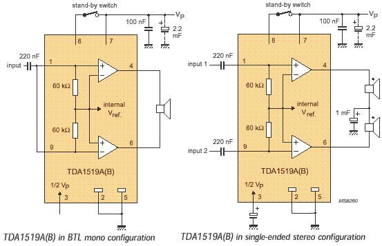
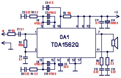
The audio amplifier circuit is based on the TDA1519 amplifier IC, which is designed for audio applications. The TDA1519 has a power output range of 2 to 6 watts. This amplifier is a Class B dual-output type and comes...
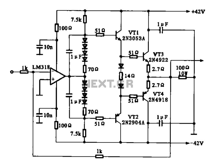
The current amplifier circuit configuration is illustrated in the figure. It consists of a two-stage operational amplifier, the LM318, arranged in a complementary push-pull amplifier configuration, which exhibits low output resistance and possesses load capacity features. The current amplifier circuit...
The amplifier circuit is highly suitable for use in FM radio receivers. It requires a supply voltage of 8 to 25 Volt DC and can deliver a maximum output power of 0.15W. Refer to the schematic below. The described amplifier...
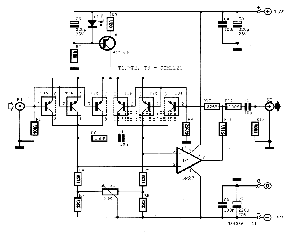
The preamplifier is designed for signal sources such as low-impedance moving coil cartridges (MC) used in high-fidelity turntables. The amplifier has an impedance of 100 ohms. To maintain low noise levels, three double-type transistors, either MAT03 or SSM2220, are...