
Current amplifier circuit configuration
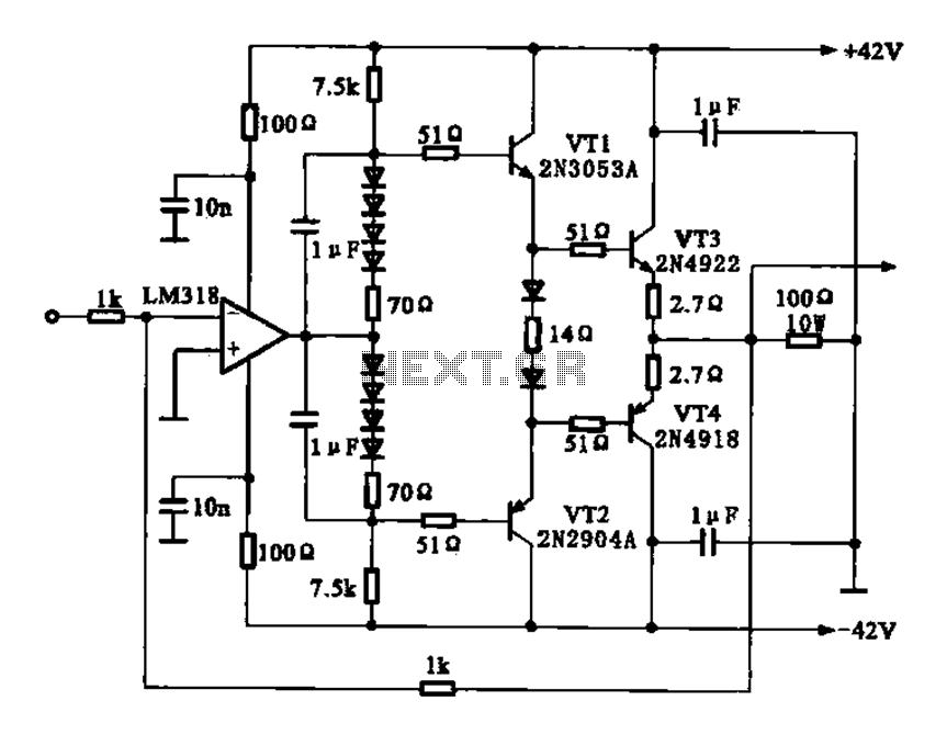
The current amplifier circuit employs the LM318 operational amplifier, known for its high performance in various applications. The two-stage configuration enhances the gain while maintaining stability and reducing distortion. The complementary push-pull arrangement utilizes both NPN and PNP transistors, which allows for efficient amplification of both positive and negative signal swings.
In this configuration, the output stage benefits from low output resistance, which is crucial for driving loads effectively without significant voltage drop. This characteristic is particularly advantageous in applications requiring high current delivery to the load, ensuring that the amplifier can maintain signal integrity even under varying load conditions.
The circuit typically includes feedback mechanisms to regulate gain and improve linearity. The feedback network can be designed to optimize bandwidth and transient response, making the amplifier suitable for a wide range of applications, including audio amplification, signal conditioning, and sensor interfacing.
Additionally, the LM318 operational amplifier features a wide supply voltage range, which allows for flexibility in design. Proper decoupling capacitors should be placed near the power supply pins to minimize noise and enhance performance. The layout of the circuit should prioritize short traces for high-frequency signals to reduce parasitic capacitance and inductance, which can adversely affect the amplifier's performance.
Overall, the described current amplifier circuit configuration is well-suited for applications demanding robust performance and reliability, thanks to its thoughtful design and the inherent capabilities of the LM318 operational amplifier.Current amplifier circuit configuration is shown in Fig., Followed by a two-stage operational amplifier LM318 complementary push-pull amplifier having an output resistance anti -low, with a load capacity features.
Related Circuits
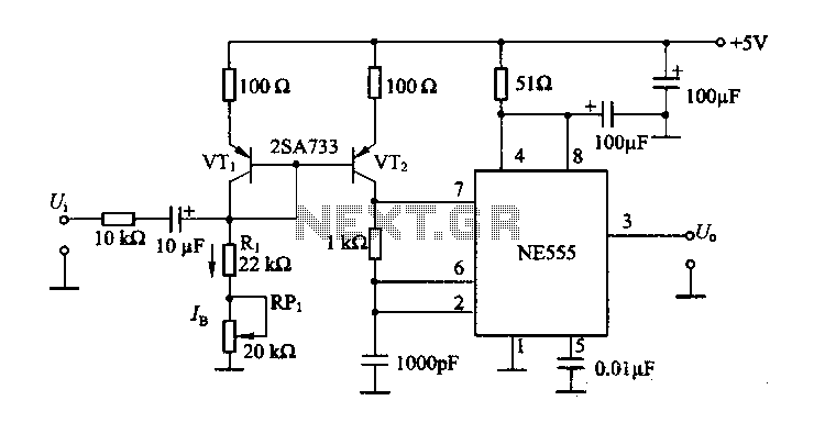
The circuit consists of a NE555 timer and a frequency modulation circuit that modifies the self-excited multivibrator NE555 by adjusting the charging current for frequency modulation. The components VT1 and VT2 form a current mirror circuit, which generates a...
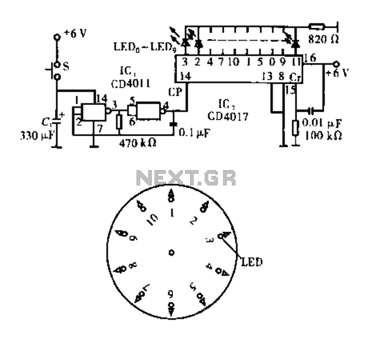
Dot Award. This circuit is tested and functional. The circuit consists of two integrated circuits (ICs). IC1 serves as a pulse source, activated by a momentary button switch (S). When the button is pressed, it charges capacitor C1, which...
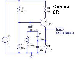
An oscillator circuit capable of generating a high-quality sine wave with a frequency of at least 500 MHz, intended for RFID applications. There have been attempts to utilize a class E oscillator, but the design has not yet been...
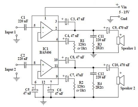
This circuit is based on the BA5406 audio integrated circuit and is capable of providing a maximum output power of 3 watts per channel. This audio circuit is designed for various applications requiring amplified sound output. The BA5406 is a...
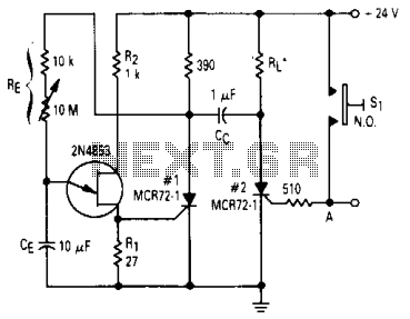
After one cycle of operation, SCR1 will be activated, resulting in a low voltage being applied to the UJT emitter circuit, which interrupts the tuning function. When pushbutton SI is pressed, or a positive pulse is applied at point...
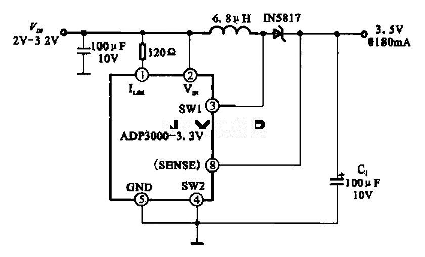
Boost 3.5V regulator circuit. This chip can boost or create a stable voltage supply from approximately 3V DC to a DC voltage of 3.5V. The boost regulator circuit is designed to increase a lower DC voltage, specifically from around 3V...
Warning: include(partials/cookie-banner.php): Failed to open stream: Permission denied in /var/www/html/nextgr/view-circuit.php on line 713
Warning: include(): Failed opening 'partials/cookie-banner.php' for inclusion (include_path='.:/usr/share/php') in /var/www/html/nextgr/view-circuit.php on line 713