
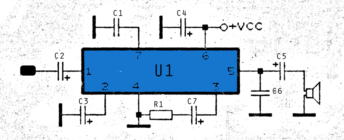
015Watt amplifier schematic
The described amplifier circuit is designed to enhance signal strength in FM radio receivers, which is crucial for maintaining audio clarity and reducing noise. The operational voltage range of 8 to 25 Volts DC allows for versatility in various applications, accommodating different power supply configurations commonly found in consumer electronics.
The circuit typically includes a transistor or operational amplifier configured to amplify weak RF signals received by the antenna. Key components may include resistors to set the gain, capacitors for coupling and decoupling, and possibly inductors for tuning purposes. The output stage is designed to deliver up to 0.15W, making it suitable for driving small speakers or headphones directly.
In terms of performance, the circuit should be optimized for low distortion and a wide frequency response to ensure that the audio output remains faithful to the original broadcast. Proper layout considerations, such as minimizing ground loops and shielding sensitive components, are essential to maintain signal integrity.
The schematic would illustrate the interconnections between these components, providing clear guidance on component values and configurations necessary for achieving the desired performance. This amplifier circuit can be an essential building block for hobbyists and engineers working on FM radio projects, enhancing the overall listening experience.Amplifier circuit is also very suitable when used in fm radio receiver. Supply voltage required 8 - 25 Volt DC with a maximum output power 0. 15W. See Schematic below. 🔗 External reference
Related Circuits
This is the schematic of the final design including the tone stack but leaving out the volume, balance, and sonic controls. The right half of the circuit is John Broskie's original White cathode amplifier with a pair of 5687s...
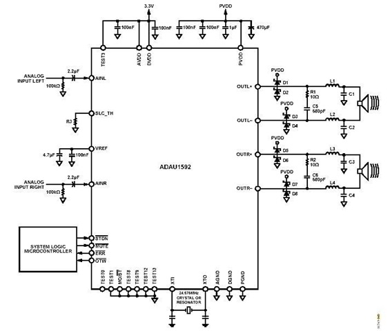
This is a stereo circuit schematic of the ADAU1592, a 2-channel, bridge-tied load (BTL) switching audio power amplifier. The ADAU1592 can be utilized in compact television sets, PC audio systems, and mini-component applications. According to the ADAU1592 datasheet, an...
The roles of capacitors C1, C4, and C5 in a circuit may not be immediately clear. Capacitors on the power rail help to smooth out the signal by reducing current ripple, which can be observed using an oscilloscope. Resistors...
The increase in industrial and computerized equipment that utilizes programmable memory has heightened the demand for reliable recording media. Currently, magnetic tape is one of the most prevalent methods. The essential element of any magnetic recording system is the...
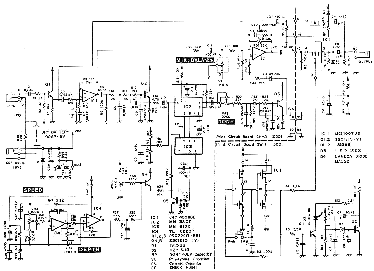
The Pearl CH-02 Chorus is a discontinued pedal known for its exceptional sound quality. It features four knobs: DEPTH, SPEED, TONE, and MIX BALANCE. The TONE knob specifically adjusts the tone of the effect sound, while the MIX BALANCE...
This is a 2x60W LM4780 Power Amplifier. The LM3886 was initially considered for this project due to its acclaim in previous designs. However, feedback suggested a need for a complete device. The LM3886 integrated circuit was difficult to source,...