
Building a Better Cam Trap
The RC-CAM2 system is designed to provide an efficient and cost-effective solution for transmitting video wirelessly from a flying model, such as a drone or remote-controlled aircraft. The system likely incorporates a combination of a camera module, a video transmitter, and a receiver unit that can be integrated into the model.
The camera module is expected to be lightweight, with a resolution suitable for real-time video transmission. It may utilize CMOS technology for low power consumption and high frame rates. The video transmitter is likely to operate in the 5.8 GHz frequency band, which is commonly used for FPV (first-person view) applications, ensuring minimal interference and a stable video feed.
The assembly process may involve securely mounting the camera on the model, connecting it to the video transmitter, and ensuring that the transmitter is powered adequately, possibly through the model's battery system. The receiver unit can be connected to a display device, such as a monitor or FPV goggles, allowing the operator to view the video feed in real-time.
The design should also consider the weight distribution and aerodynamics of the model, as additional components can affect flight performance. Proper antenna placement for the transmitter and receiver is crucial to maximize range and minimize signal loss.
Overall, the RC-CAM2 system represents a significant advancement in wireless video technology for remote-controlled models, providing enhanced performance and affordability, while requiring some user engagement in the assembly process to ensure optimal functionality.The improved system is called RC-CAM2. It works better AND it costs less than my earlier attempt to get a wireless video system on my flying model. The only caveat is that there is some assembly (or disassembly as you will soon find out) required. 🔗 External reference
Related Circuits
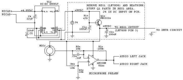
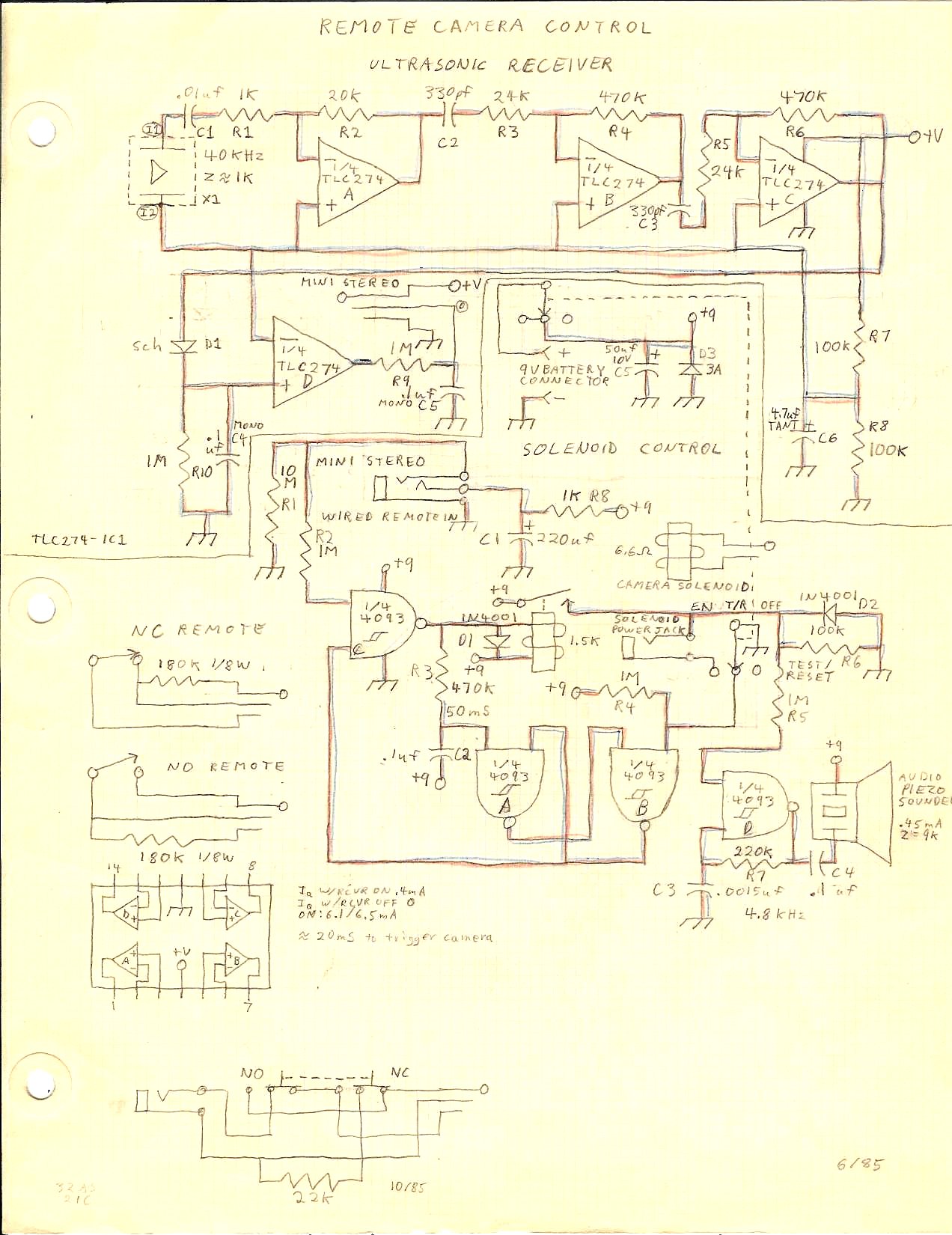
This version of the trigger circuit for the stop-motion camera system utilizes an electret microphone for sonic input, although it can be replaced with an LED and photodiode pair for optical triggering. A recent home-built project involved constructing a...
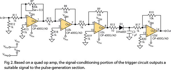
There is no prior experience in building controllers, and there is uncertainty about how to begin. A budget constraint of less than 100 euros is present. A power thyristor is already available. The inquiry revolves around the best method...
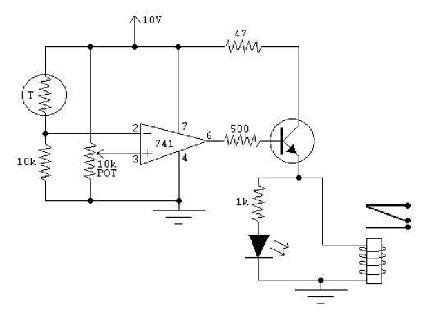
Lightning Activated Camera Shutter Trigger. This picture was taken using the circuit. This circuit is used to trigger a camera's electronic shutter circuit when a flash occurs. The Lightning Activated Camera Shutter Trigger is designed to capture images of lightning...
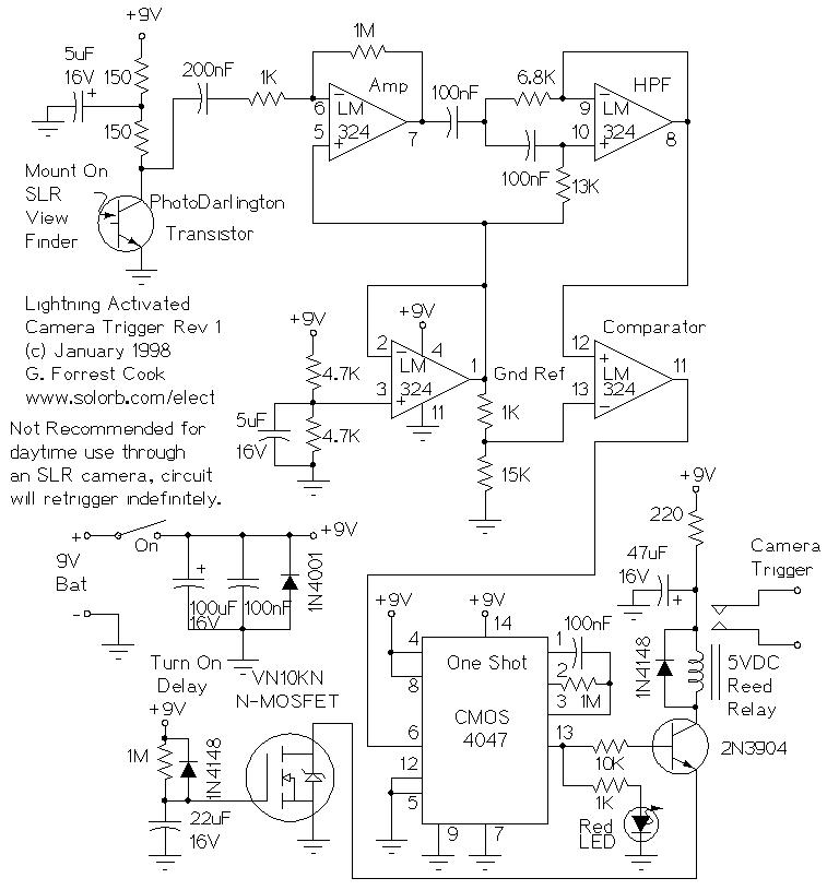
A camera trigger designed to capture transient phenomena was created using a Mamiya ZE 35mm camera and a Mamiyalite ZE flash unit. At that time, the only method for remotely triggering the camera was through the cable release socket...
This circuit can be used for multiple cameras with one monitor. The circuit can be operated manually or automatically. The described circuit functions as a video switching system, enabling the connection of multiple camera inputs to a single monitor output....
The two optical sensors will provide a count of individuals to the microcontroller, which will relay this value to MCU-II. The microcontroller will detect the entrance of any person through high-to-low pulse transitions on input pins A3 and A4. The...