
Camera Switcher
The described circuit functions as a video switching system, enabling the connection of multiple camera inputs to a single monitor output. This configuration is particularly useful in surveillance applications, where multiple camera feeds need to be monitored simultaneously or switched between as required.
The circuit typically includes a selection mechanism, which can be implemented using either mechanical switches for manual operation or electronic components such as relays or transistors for automatic operation. In a manual setup, a rotary switch or push-button switches allow the user to select which camera feed is displayed on the monitor. In an automatic configuration, a microcontroller or timer circuit can be employed to cycle through the camera feeds at predetermined intervals or based on specific triggers, such as motion detection.
Key components of the circuit may include:
- **Cameras**: Each camera should be compatible with the chosen video format (e.g., NTSC, PAL) and have the necessary power supply.
- **Multiplexer or Switch**: A video multiplexer can be used to handle multiple video inputs, allowing for seamless switching between feeds. Alternatively, analog switches or relays can be used for simpler applications.
- **Monitor**: A single video monitor capable of displaying the output from the selected camera. The monitor should support the video format being used.
- **Control Logic**: For automatic operation, a microcontroller (e.g., Arduino, Raspberry Pi) can be programmed to manage the switching logic, controlling the multiplexer or switch based on predefined criteria.
Power supply considerations are crucial, as adequate voltage and current must be supplied to all cameras and active components. Signal integrity should also be maintained, requiring the use of appropriate cabling and connectors to minimize interference and ensure high-quality video transmission.
Overall, the circuit’s design should prioritize user-friendliness and reliability, ensuring that the switching mechanism functions smoothly whether operated manually or automatically.This circuit can be used for multiple cameras with one monitor. The circuit can be operated manually or automatically. 🔗 External reference
Related Circuits
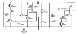
The circuit diagram illustrates the original Kodak MAX Flash Unit, including the semiconductors that comprise the circuit. This diagram represents the unmodified version intended for the standard Kodak model, which should closely resemble the Kodak MAX model, if not...
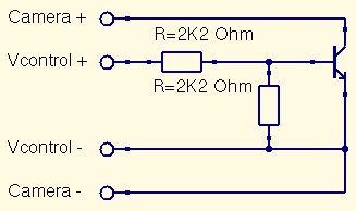
This is a straightforward guide to constructing a digital switch for a camera, enabling photo capture through microcontrollers. Required components include: 1. A digital switch for a camera can be implemented using a microcontroller, such as an Arduino or...
The photometric camera for the SDSS consists of two TDI scanning CCD arrays: one featuring 30 Tektronix/SITe 2048 x 2048 CCDs arranged in a 5 by 6 array for five-color photometry, and the other composed of 24 2048 x...
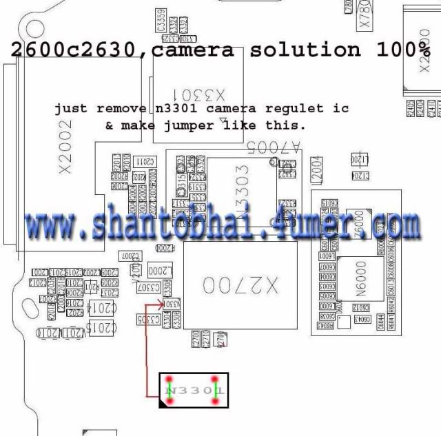
The camera operation failure on the Nokia 2630 has a similar solution to that of the Nokia 2600c, as both devices share the same circuit board. This issue is typically caused by hardware damage or a broken line on...
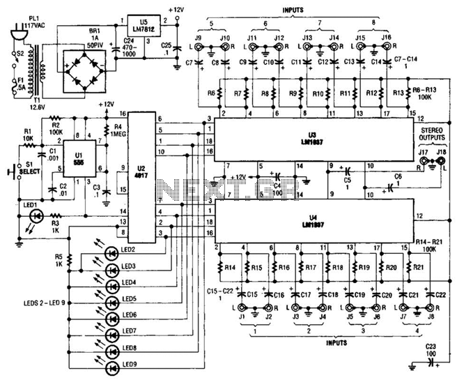
This source is selected by pressing a momentary-contact pushbutton switch (SI). Switch SI is connected to the trigger of a 555 oscillator/timer (U1) configured as a monostable multivibrator, which generates one short output pulse for each press of SI....

A radio camera on a model railway should transmit constantly while the train is moving and continue transmitting for a few minutes after the train stops. The design of a radio camera system for a model railway requires careful consideration...