
Built-in battery charger, Li-Ion


The described circuit functions as a built-in charger for lithium-ion or lithium-polymer batteries, ensuring efficient charging while maintaining temperature stability. The charger employs a series of transistors and resistors to regulate the charging process and monitor battery voltage.
The core of the circuit is the transistor T4, which operates as a switch rather than a voltage follower. When the charging voltage exceeds a specific threshold, T4 closes, preventing current from flowing through the divider resistors R4 to R6. The base-emitter junction of T1 is reverse-biased, allowing it to conduct a small reverse current. When a charging voltage of at least 4.9 V is applied, T1 produces a voltage approximately 0.5 to 0.6 V higher than the battery voltage, effectively regulating the charging process.
The TL431 voltage stabilizer IC1 plays a crucial role in maintaining a stable output voltage of around 2.5 V, which is necessary for the operation of T4. The charging process transitions from a constant current phase to a constant voltage phase, with the resistor R1 dropping approximately 0.5 V during the constant current stage. This resistor also serves to indicate the charging status through the LED connected to T5, which turns on when the voltage across R1 and D1 exceeds the threshold necessary to activate T5.
The circuit design includes provisions for adjusting the charging voltage through resistors R4, R5, and R6, allowing for fine-tuning based on the battery's specifications. It is recommended to set the charging voltage between 4.1 V to 4.15 V for optimal battery longevity, particularly during the last stages of charging.
The choice of transistors, such as BSS138 for T4, ensures low threshold voltage operation, which is critical for the charger’s overall efficiency. The design also accommodates variations in power supply, eliminating the need for additional current limiting components when using wall adapters or small transformers, as these typically manage current flow effectively.
Overall, the circuit demonstrates a well-structured approach to lithium battery charging, balancing performance, thermal stability, and component selection for reliability and longevity.Build-in charger for instruments powered by single lithium-ion or Li-Pol accumulator. If external power supply not conected to charger, current back from the accu charger is very small. New version improved temperature stability and Not Needed NTC thermistor. After a simple adjustment can be from initial engagement to launch a thermistor to compensate for temperature dependence. After adjustment (see Figure 1 ) operates as a transistor T4 not voltage follower, but as a switch. If charging voltage is present, transistor T4 is closed and the divider resistors R4 to R6 does not pass any current.
Base-emitter transition T1 is polarized in the reverse direction, based on the zero voltage, so it will pass through the transistor T1 reverse current. After connecting the charging voltage of at least 4.9 V is based on the T1 will supply about 0.5 to 0.6 V greater than the battery voltage nabíjeného.
When fully charged battery (4.2 V) is based on the T1 to approximately 4.7 V. Since the input R TL431 is a voltage stabilizer of approximately 2.5 V, the transistor T4 opened voltage around 2.2 V. At this voltage transistor T4 resistance of closed and open channel of singles, up to tens of ohms and its resistance to practically apply the divider.
If the charged battery is discharged, the voltage on the basis of a smaller T1 and T4 may not be fully opened. It does not matter, because at this stage the battery is recharged as the "constant stream" and stabilize the voltage to apply.
For proper function of the battery charger must have a small transistor threshold voltage of T4. Well meet transistor BSS138 (SMD) or BS108 for classical mounting. Both types have a threshold voltage of typically about 1 V with a charging current limiter transistors T2 and T3 has been described in detail here and I will not repeat it here. If you use the charger power supply with a small transformer or a small power adapter into the wall, there is no need to limit the current in the charger, it takes care of power supply.
You can then use the simplified connection a charger, which is the figure 3 . It should just check that the charging current is not greater than the maximum allowed, usually 0.5 C. For completeness, the chargers in Figure 1-3 runs a small reverse current (max. 120 mA) when the input voltage charger is slightly smaller than the battery voltage ( Fig. 4 ). Because in practice this situation does not occur consistently (power supply is connected or disconnected), it is not at fault.
The charging voltage after treatment is no longer dependent on the threshold voltage of T4 and thermistor resistance. Thermal stability is determined practically only the stability of IC1. Therefore, it was removed from involvement Trimmer and charging voltage is set to fixed resistors R4 to R6.
If you omit the (shorted) resistor R5, the final charge voltage usually slightly larger than 4.2 V. By connecting a resistor R5 can adjust the voltage to the required size. Just when you charge the battery for 90 to 95%, we recommend setting the charging voltage of 4.1 to 4.15 V. At lower charging voltage is very significantly increases the number of charge cycles and prolonged battery life.
When charging, at "constant stream" is the resistor R1 voltage drop of about 0.5 V, the charging phase "constant voltage" gradually decreases to zero. This offers a possibility to indicate the charging process. This circuit is the transistor T5 and a diode D1 in connection to Figure 2 . It flows through a resistor R1 current, the sum of the voltage drop on R1 and D1 threshold voltage greater than the voltage needed to open the transistor T5.
T5 is opened the current flowing in the resistor R7. Current through the resistor R8, the LED lights to indicate battery charging. In constant voltage charging phase decreases the charge current and voltage drop across the resistor R1 decreases. Reduces the loss of a close to zero, the current passes through the resistor to the base of T5, but the diode D1.
At the end of the charging LED brightness slowly fades until almost a full charge goes off. The D1 site I originally used a Schottky diode (compared to about half the normal voltage drop), but the LED has extinguished the transition from constant current charging phase to the phase constant voltage charging, the battery is not fully charged. R1 2.2 Ohm, SMD 1206 (for 230 mA, 4.7 ohms for 110 mA) R2 470 Ohm, SMD 1206 R3 100 Ohm, SMD 1206 R4 22 Ohm, SMD 1206 R5 680 Ohm, SMD 1206 see text R6 15 Ohm, SMD 1206 T1 BCP68-25 T2, T3 BC857 (code 3F) T4 BSS138 (SS or code J15) IC1 TL431C SMD PCB bcs53
🔗 External reference
Related Circuits
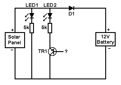
A small solar panel is used to maintain a 12V car battery. The panel provides approximately 75mA of current to the battery under full sunlight conditions. The described circuit employs a solar panel specifically designed for battery maintenance applications. The...
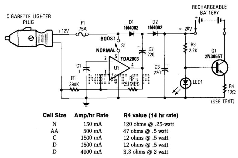
This circuit provides an output of up to 20 V from a 12-V automotive supply, enabling constant current charging of NiCad battery assemblies with a total voltage of approximately 18 V. The circuit utilizes a square-wave oscillator (VI) and...
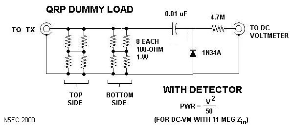
This is a variation of the "parallel resistor" dummy load. It is designed for QRP HF operation of 5 watts or less average power and is suitable for continuous operation at that level. The dummy load is compact, measuring...
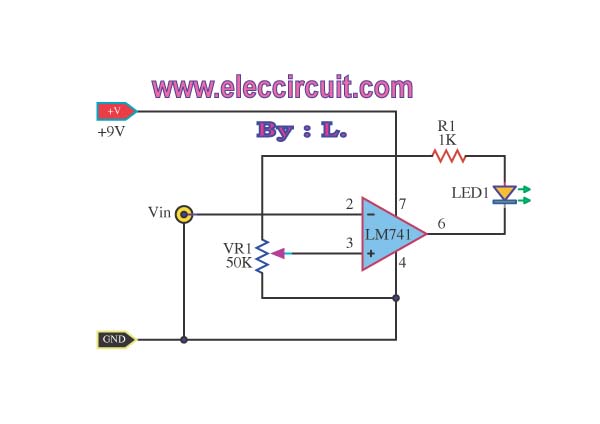
This simple low voltage tester circuit can be used to monitor batteries and other voltage sources for issues, utilizing an LED display and alarm sound. The low voltage tester circuit is designed to provide a reliable method for monitoring the...
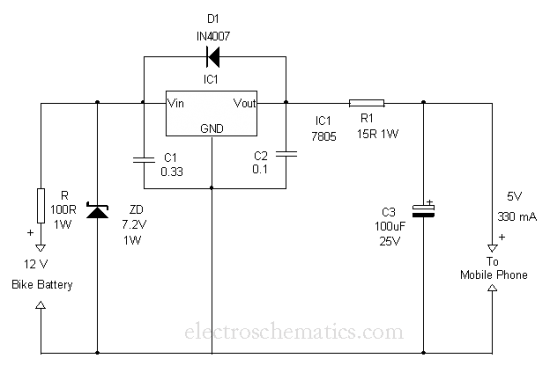
This is a simple and easy method to extract current from a motorcycle battery to charge a mobile phone. Most mobile phone battery packs consist of three 1.2 V cells. To effectively tap current from a motorcycle battery for mobile...
Typically, a charged lead-acid battery and a power inverter are utilized to ensure a well-organized holiday where family members can enjoy their electric and electronic devices. With rechargeable lead-acid batteries, it is often beneficial, if not essential, to determine...